PPC Overclocking Station
Last updated: January 7, 2022
I figured I have enough materials to slap a page together with all the resources on it. This page will be updated over time as I overclock more.
If you want to know about power supplies have a look here for pinouts etc. (link coming at some point)
While I have personally tested/used most of the information on this page, there may be wrong information. Also by overclocking your CPU, you may damage it beyond repair. The risks are yours and I am not responsible for any issues that come from using the information on this page. With that out of the way, enjoy!
Jump to:
• Overclocking the iMac G3
• Overclocking the Power Mac G3 B&W
• Overclocking the Mac mini G4
• Overclocking the PowerBook G4 (15-inch Double-Layer SD)
• Overclocking the Power Mac G4
• Overclocking the Power Mac G4 QuickSilver (Single-CPU)
• Overclocking the Power Mac G4 QuickSilver (Dual-CPU)
• Overclocking the Power Mac G4 MDD (Dual-CPU)
• Overclocking the Sonnet Duet 1.8GHz (MDD/X-Serve Model)
Overclocking the iMac G3
Overclocking the Power Mac G3 B&W
Overclocking a G3 B&W is remarkably easy. This was the first overclock I ever did back in 1999.
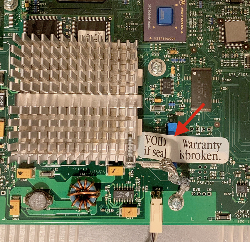
Open the Mac and locate the CPU heat sink. Next to it is a blue block with a “VOID warranty if seal is broken” sticker over it. This sticker may be missing on your G3 but typically if it has never been removed and put back, the original glue is still holding this sticker firmly in place. There are systems where the jumper block is under a white cap but the rest of this article will use blue.
Before you remove the sticker and void your warranty, which may be almost about to run out at this point anyway.. take note of the blue cap. One corner has a bump on the side and the number “1” printed n the board under it.
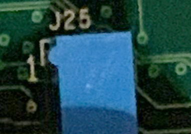
This indicates the first pin in the jumper block that is hiding under the blue cap. Now even if you drop the blue cap and don’t remember in which orientation it came off, you can put it back the right way. With that noted, go ahead and remove the sticker if present. Now note the fun print on the board next to the jumper block:
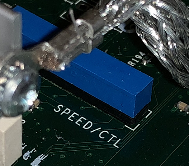
Oh yeah! “SPEED/CTL”, it tells you exactly where to go to mess with the speed settings on this thing, isn’t old tech awesome?!. Remove the blue cap and turn it over, you should now be looking at something like this:
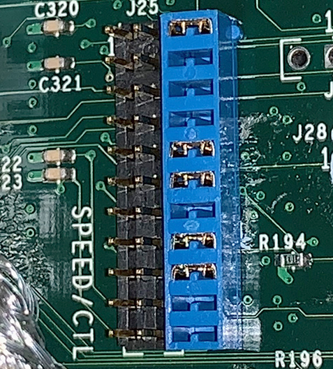
The G3 used in this example is a 350MHz model. If your G3 is a different clock speed, these jumpers will of course be different for you. Now remember the notch on the blue block, this is pin/jumper number 1. Oriented just like seen in the photo, here is the jumper block:
Jumpers 5-11 are to set the bus speed. This will not change regardless of the speed you pick so you are left with 1-4 (red below) to set your new clock speed. With that in mind, here are the jumper settings and speeds:

I’ve done 100MHz on top of the original clock speed but never pulled off 150MHz, typically I stuck with a 50MHz overclock for stability and reliability sake. So with the fastest B&W sold being a 450Mhz, you should not need any of the jumper settings for 550MHz+. However maybe someone out there still wants to give it a shot and actually succeed at pushing a 450MHz to 700, so I included all jumper options up to 800MHz.
Back in ’99 I used a piece of tin foil to get the job done. Today with eBay and other options I did not have at the time, you may be able to find some actual jumpers for this project though. Greg Hrutkay mentioned that SCSI jumpers will get the job done. Pry the metal from those jumpers to use or leave the Blue/White block off and use these jumpers instead. Use a pushpin or needle to remove and reposition jumpers if you need to, this should keep them intact. Make sure to thoroughly test reliability after the overclock and go back 50MHz if you spot trouble. Good luck!
Overclocking the Mac mini G4
The Mac mini G4 has a 167MHz bus which can not be changed, so five clock speeds are possible for the CPU.
1.25, 1.33, 1.42, 1.50 and 1.58GHz.
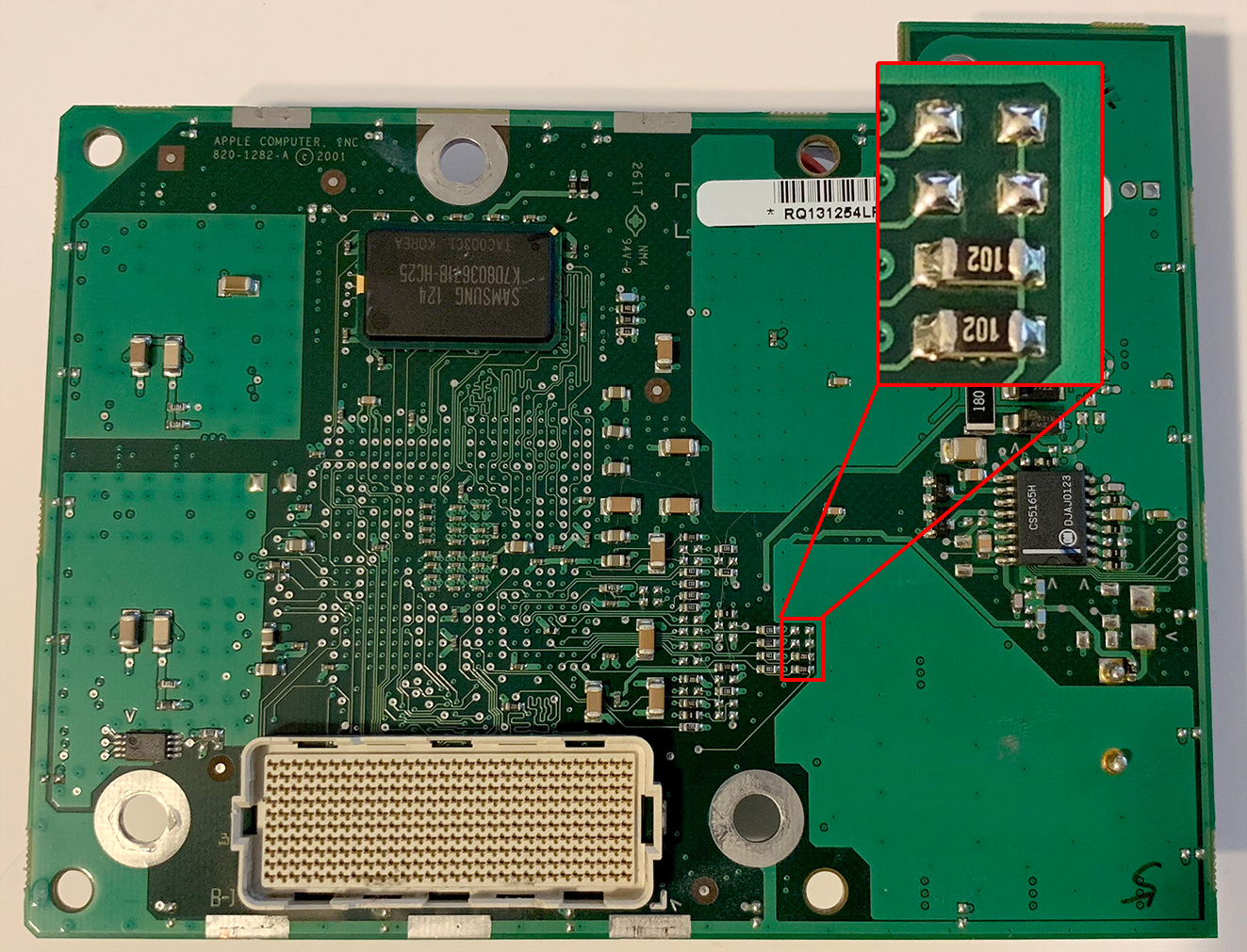
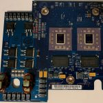
With the board removed from the Mac mini, flip it over and look for the clock speed jumpers (click to enlarge if needed).
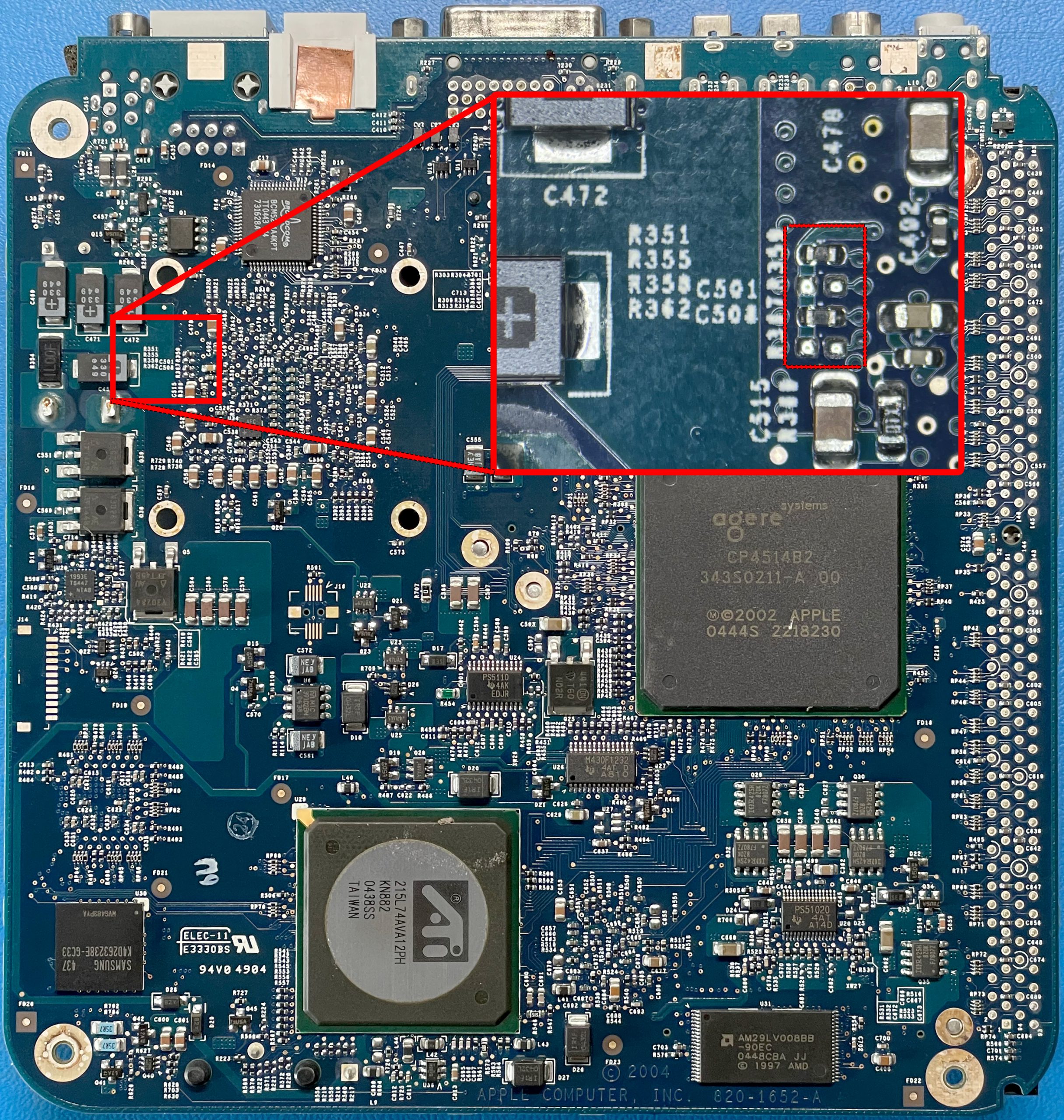
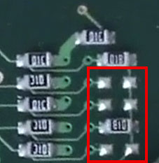
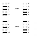
You’ll find space for 4 resistors. Keeping the board oriented as shown in the photo, these are the jumper settings for the corresponding clock speeds:
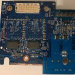
To set the jumpers for 1.33GHz, a 5th resistor has to be located (as it needs to be removed).
With the 5th resistor, for now, permanently enabled, you can only configure for the 4 clock speeds shown above. A common belief is that the 5th resistor is always enabled and acts as a ground but that does not work as the 1.33GHz configuration needs that resistor removed. Comparing a 1.33GHz board with another G4 mini board should help in locating that 5th resistor. Once this is located I will update this page.
All of these speeds should be possible without having to mess around with voltage changes etc. While the CPU heatsink does not need to be removed for this overclock, I do recommend removing it so that dust can be cleaned and fresh thermal paste can be applied.
Overclocking the Power Mac G4
Overclocking the PowerBook G4 (15-inch Double-Layer SD)
Overclocking the Power Mac G4 QuickSilver (Single-CPU)
QuickSilver G4’s are all 133MHz bus systems, use only the jumper settings as mentioned in this section, mixing them up with those for the MDD can damage your CPU card. For good measure, here are the systems:
Power Mac G4 (QuickSilver) – 1 x 733MHz
Power Mac G4 (QuickSilver) – 1 x 867MHz
Power Mac G4 (QuickSilver 2002) – 1 x 733MHz
Power Mac G4 (QuickSilver 2002) – 1 x 800MHz
Power Mac G4 (QuickSilver 2002) – 1 x 933MHz
Power Mac G4 (QuickSilver 2002ED) – 1 x 867MHz
On the single CPU cards, the clock setting jumpers are on the back side of the card. Shown below is a single 733 and 867MHz CPU card and the jumper positions.
Clock Speed
You may have an additional row of resistors on the single 800MHz and single 933Mhz CPU card. Just ignore them and focus on the bottom four as shown in this picture.
Voltage
Voltage changes can be made by the CPU buck controller, found also on the back side of the 733MHz and 867MHz CPU card.
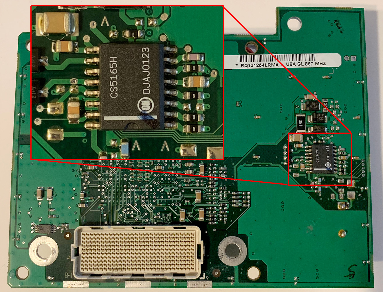
VID3 and VID4 are always connected. There are many more voltage options for this chip but the ones below are what is used by the CPU’s from Apple, with 2.10V being the maximum the 867MHz CPU can handle. If/when I get details on other CPU cards this information may be adjusted though. Do not follow these settings unless the chip reads model number “CS5165H“!
The below chipset and settings are applicable to the following confirmed cards:
• 1 x 733MHz (Thank you Blake Hanes)
• 1 x 867MHz

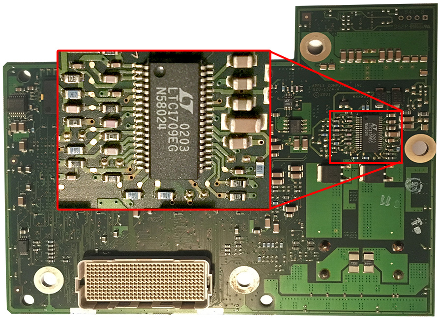
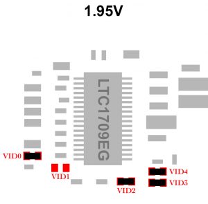
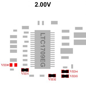
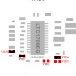
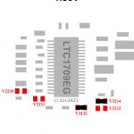
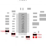
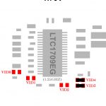
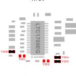
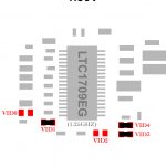
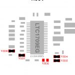
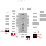
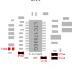
The single 800MHz and single 933MHz CPU cards use the same voltage regulator chip as some of the dual CPU MDD cards marked “LTC1709EG” but the board layout is different. Since I don’t have the physical card to take measurements of the chip, no voltage settings are available yet. From images I can clearly see where VID2, VID3 and VID4 connect to but VID0 and VID1 do not have a clear connection to anything. I have a good guess that makes me 95% sure and could use some help. Below is where the voltage jumpers can be found on the single 800/933MHz cards:
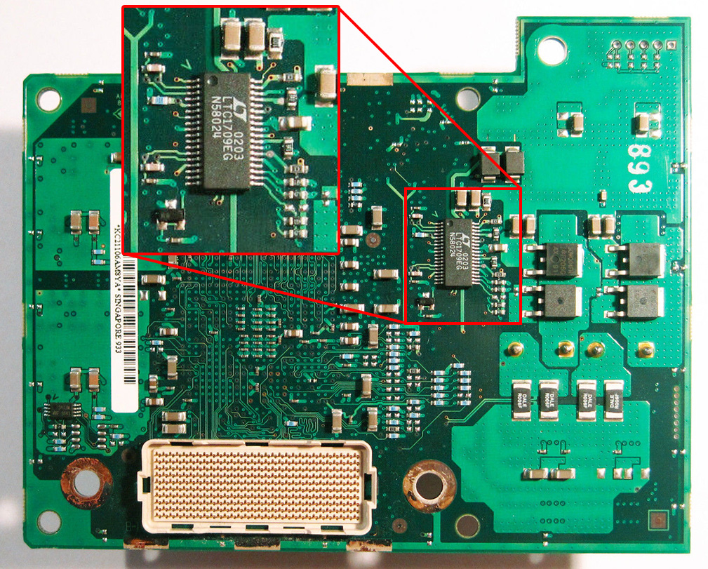
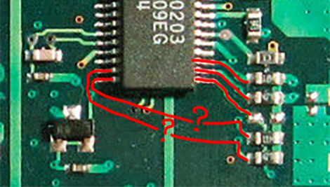
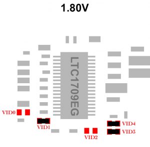
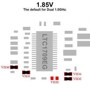
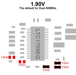
According to the LTC1709EG diagram, these are the VID pins (excuse the poor image quality):

As you can see, it’s obvious where VID 2-4 connect to. VID0 and 1 not so much. Now I am almost positive that VID0 and VID1 connect to the two resistors underneath VID2 (which makes the voltage of the card in the picture 1.85V) but until I have confirmation from someone checking with a multimeter, I don’t want to post the final graphics. If you can help out, let me know!
Overclocking the Power Mac G4 QuickSilver (Dual-CPU)
Systems
As a reminder; all QuickSilver models are 133MHz bus speed.
Power Mac G4 (QuickSilver) – 2 x 800MHz
Power Mac G4 (QuickSilver 2002) – 2 x 1.0GHz
Clock Speed
The dual 800MHz card has the jumpers labeled which makes them easy to find. Here are the locations on each side of the card. Thank you to Feliciano Vargas for the photos!
Front:
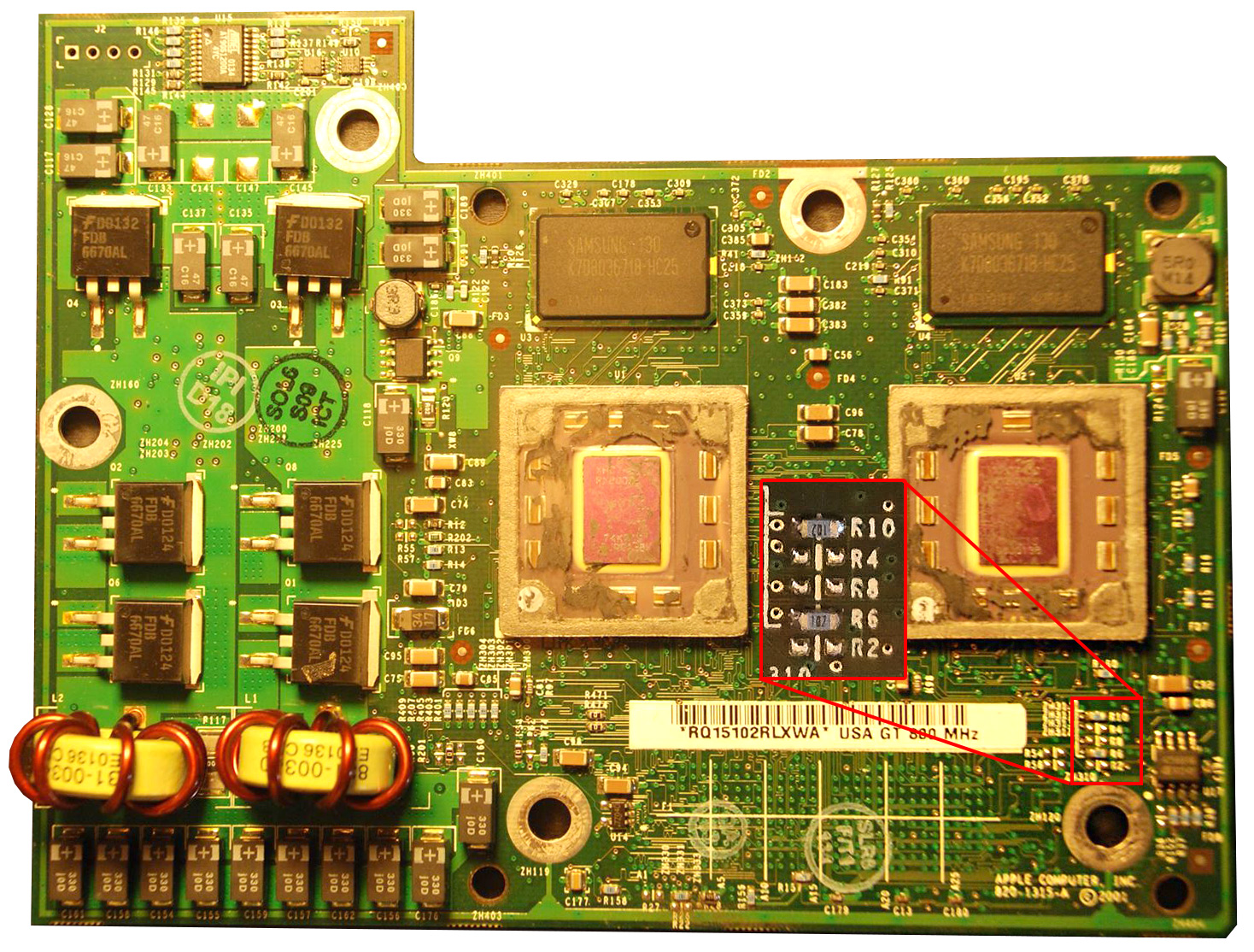
Back (awaiting a good detail photo for the zoom, enhancement will have to do for now):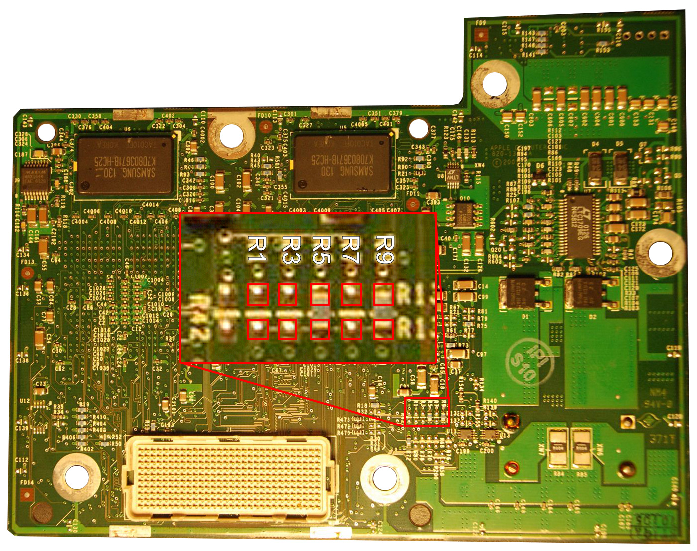
So on the front we have R10, R4, R8, R6 and R2. On the back we have R9, R7, R5, R3 and R1. This is the same jumper labeling as found on the dual CPU MDD cards and the same settings apply.
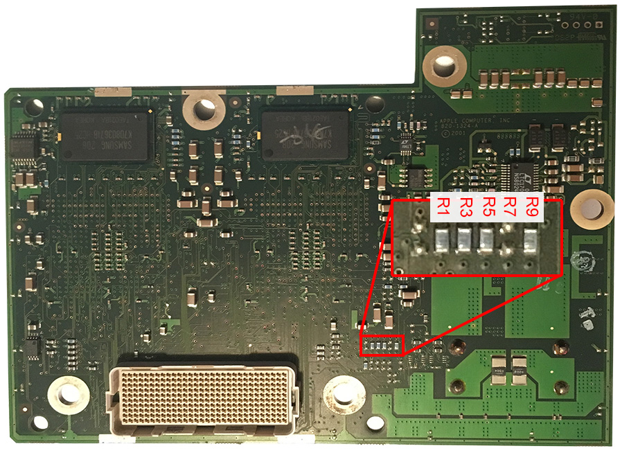
For the dual 1.0GHz card, the jumpers are not labeled. Below are the locations on each side of the card with labels added. Thank you Greg Hrutkay for the photos!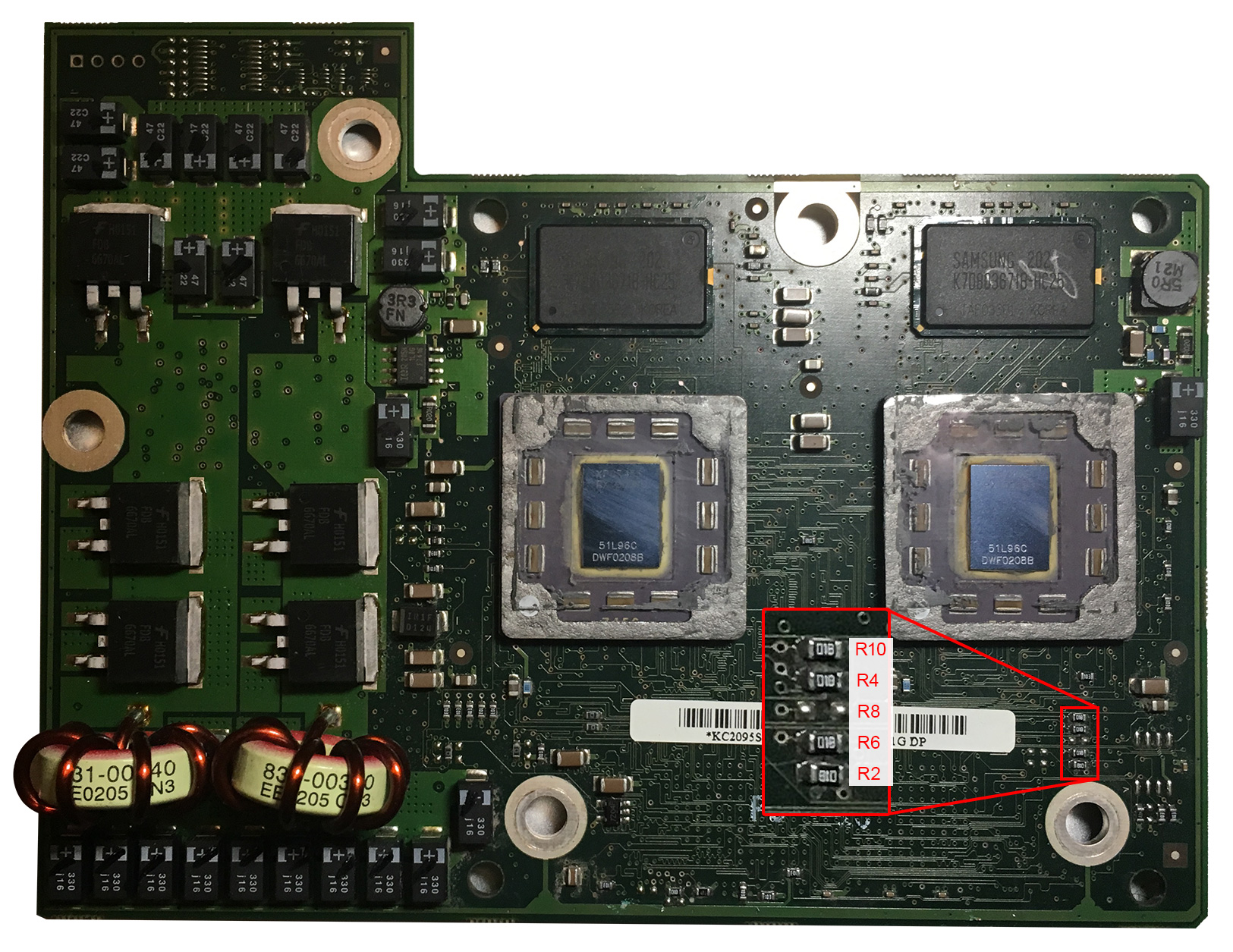
And here on the back of the card:
To match the picture orientation and bus speed (133MHz) of the above photos, here is a graphic specifically for the Dual 800MHz and Dual 1.0GHz QuickSilver CPU cards (click for full size):
NOTE: The dual 800MHz already runs at near maximum voltage (1.90V) by default so you may not be able to overclock this specific card very far.
Voltage
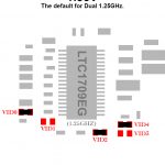
The Dual 800MHz and Dual 1.0GHz CPU card also uses the same voltage regulator chip as some of the single CPU QS cards and dual CPU MDD cards marked “LTC1709EG” but the board layout is again different. Here’s what to look for:
And here are the voltage settings (not including many of the voltages below the cards defaults):
Overclocking the Power Mac G4 MDD (Dual-CPU)
What you bussin’ at?
Here is a list of models and bus speeds. This list assumes a stock system.
Power Mac G4 (Mirrored Drive Doors) – 2 x 867Mhz – 133MHz
Power Mac G4 (Mirrored Drive Doors) – 2 x 1.0GHz – 167MHz
Power Mac G4 (Mirrored Drive Doors) – 2 x 1.25GHz – 167MHz
Power Mac G4 (FW 800) – 1 x 1.0Ghz – 133MHz
Power Mac G4 (FW 800) – 2 x 1.25Ghz – 167MHz
Power Mac G4 (FW 800) – 2 x 1.42Ghz – 167MHz
Power Mac G4 (Mirrored Drive Doors 2003) – 1 x 1.25GHz – 167MHz
Power Mac G4 (Mirrored Drive Doors 2003) – 2 x 1.25GHz – 167MHz
Before you start overclocking, it’s important to know if your system is running at 133MHz or 167Mhz bus speed. Following the below overclocking jumper settings (all based on 167MHz bus speed) will have a very different result on a 133MHz bus speed CPU card or system. The good news is that (as far as I know), any 133MHz G4 system can be easily modded to become a 167MHz system. You need to remove a resistor on your Mac’s logic board and also check the CPU card to see if that needs to be modded. Keep in mind that if your system is currently running at 133MHz bus speed and uses PC-2100 SDRAM, you’ll want to have PC-2700 SDRAM ready to go once your system runs at 167MHz bus speed for good reliability/stability.
Checking bus speed the easy way
If you’re running Mac OS X, open System Profiler and see if the bus speed is listed in the information. Mac OS 9 may also show the bus speed information.
Checking bus speed the not so easy way
Both your CPU card and logic board need to be checked, both have a small block of jumpers that dictate the bus speed. On the CPU card this block can be found here:
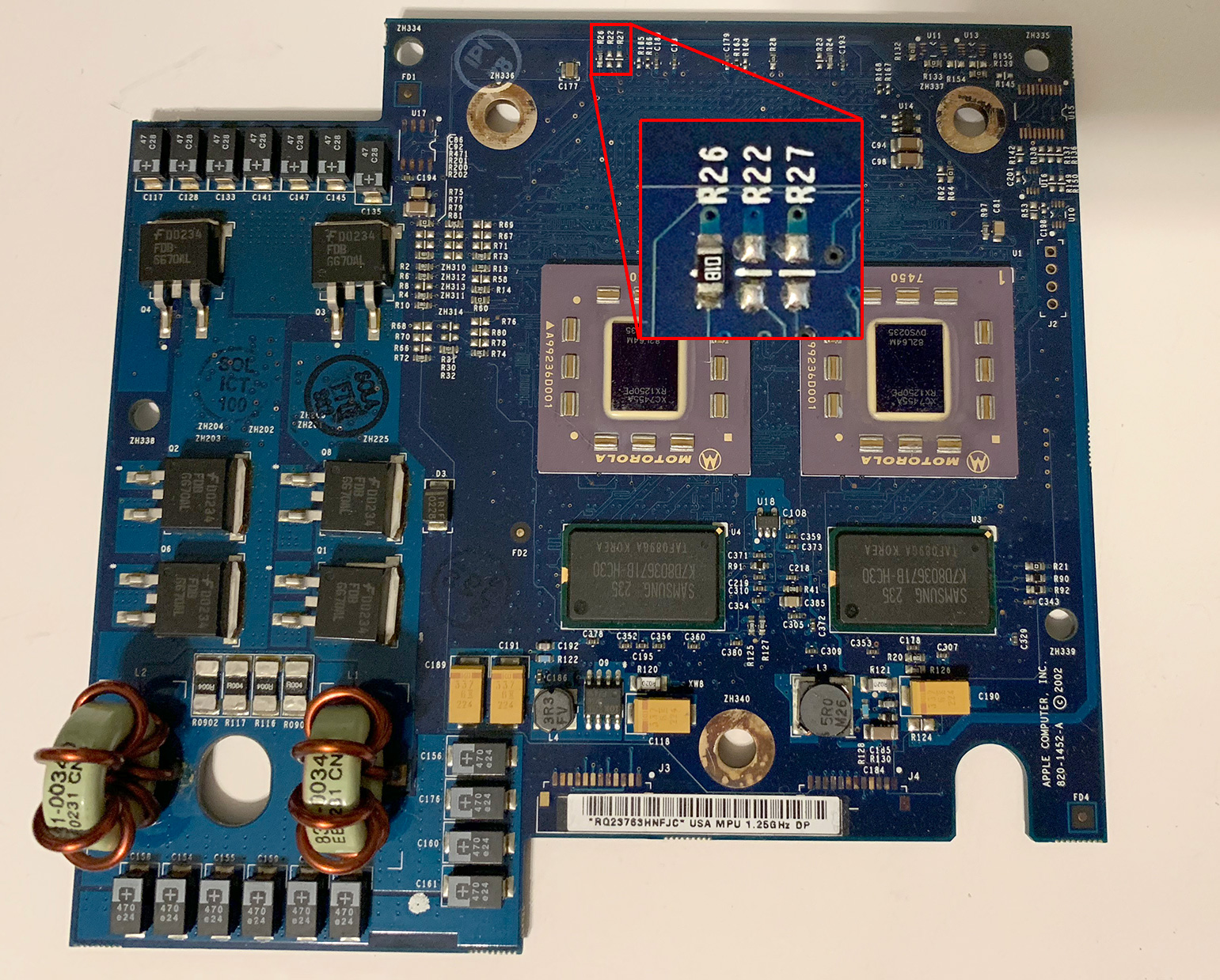
This is a photo of an original dual 1.25Ghz card which is set for a 167MHz bus speed.

Turning a 133MHz CPU card into a 167MHz CPU card is just a matter of removing the R22 resistor.
BEWARE! Changing the bus speed of your CPU card will affect the clock speed. If your CPU card was a dual 1.0GHz, it will be a dual 1.25GHz after the bus change! If your CPU card was a dual 1.33GHz, it will be a dual 1.67GHz after the bus change! While this may sound great, such big jumps in clock speed will most likely result in a system that no longer boots or kernel panics without a voltage modification as well (this is covered further down the page).
My recommendation is to:
1. Change the bus speed of your CPU card and logic board.
2. Lookup the jumper settings for the original clock speed of your card and set the jumpers accordingly.
If your CPU card was a dual 1.0GHz before the bus change, you want it to be a dual 1.0GHz still after the bus change. You won’t have to worry about voltage settings, instability or overheating if you do this. You’ll have your original clock speed just with a faster bus. This is a good foundation to work from as you proceed to overclock your CPU.
As touched on before, you will also need faster RAM for stability. 133MHz bus machines were typically limited to PC-2100 SDRAM but once you run at 167MHz you want PC-2700 SDRAM in your machine!
Of course you still have to check your Mac’s logic board to see what bus speed that is set at. Unfortunately the same jumper block you found on the CPU card, is on the bottom of your Mac’s logic board. Yup, to check and change the bus speed of the logic board it will have to come out, sorry. Click on the below photo for the full size version so you can see where to find these jumpers.
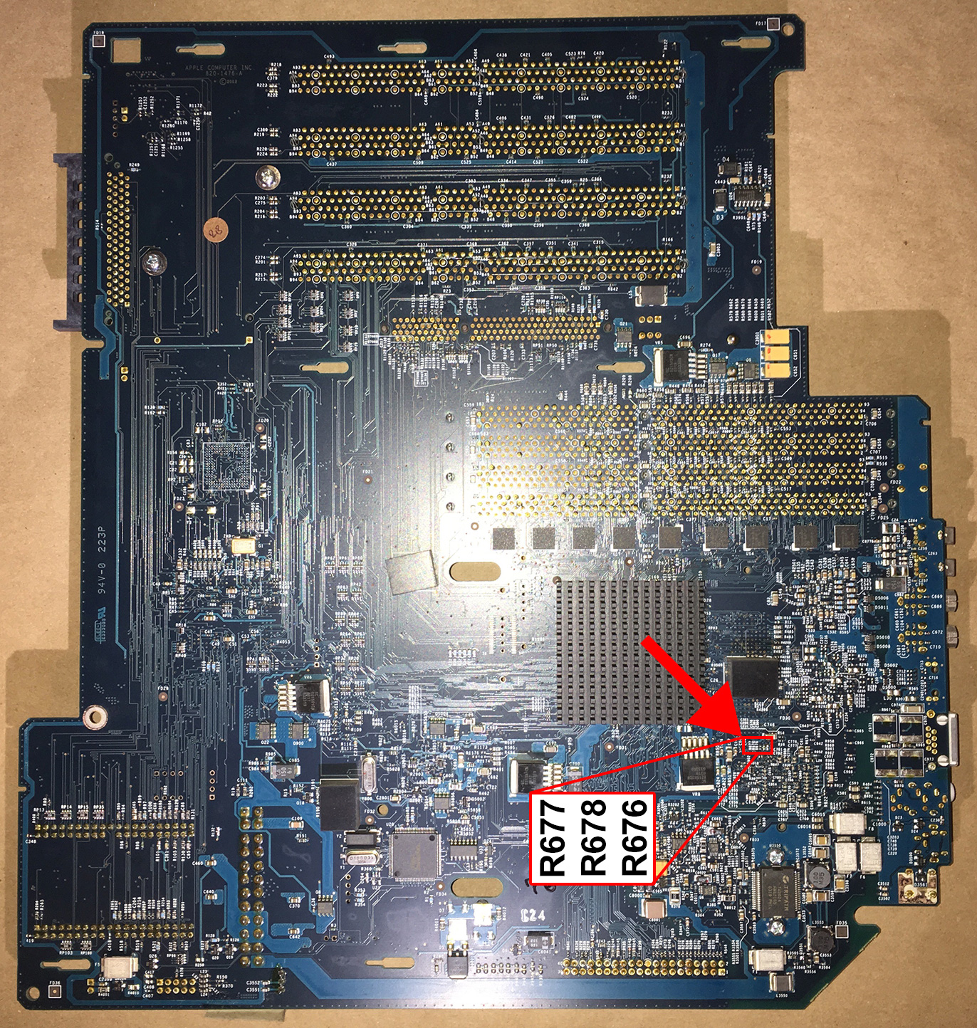
The block will be marked with R677, R678 and R676. In the case of this MDD board the markings are above the jumper pads, some boards may have these markings directly next to each pad. As far as I know they will always have the same numbers, regardless of your board layout.
With your bus now at 167MHz, time to overclock!!
The below graphics are based on the 1.25GHz Dual CPU card but should work with all dual MDD/X-Serve CPU cards 867MHz – 1.42GHz.
Clock Speed:
This graphic shows the jumper settings and resulting clock speeds for cards dual 1.0GHz and up. Try to re-use the resistors that are currently on the board. If you don’t have enough you can bridge two pads with a blob of solder or piece of wire.
Voltage:
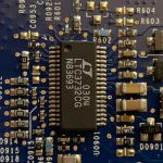
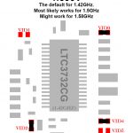
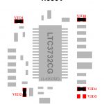
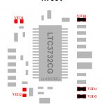
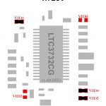
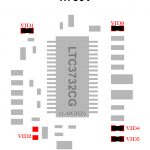
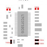
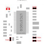
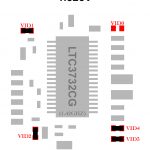
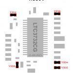
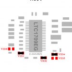
At some point the clock speed you set will require more power to function. That’s where these jumper settings come in. These jumpers can be found on the back of the CPU card and are based on a dual 1.42GHz CPU card with a voltage regulator chip marked “LTC3732CG”.


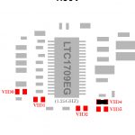
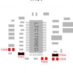
For the dual 867MHz, 1.0GHz, 1.25GHz and 1.33GHz CPU cards that have a voltage regulator chip marked “LTC1709EG”, here are the jumper settings:


NOTES:
- At 1.42GHz you should already be using the copper heat sink as it cools the best.
- Once you pass 1.5GHz, use the copper heatsink in conjunction with additional exhaust fans. Keep a close eye on the temperature of the CPU card with a tool such as Temperature Monitor 4.7.
- If you get to or past 1.58GHz it is recommended to open the case door and use a good external fan. The MDD case design is very poor so internal fans will not be able to keep the CPU adequately cooled.
- At 1.67GHz or above, definitely use external cooling. At this point you may also want to try using the large aluminum MDD heat sink (modified to fit on a 3-coil CPU) as the metal plate under the copper heatsink will get too hot and undo all the good work the copper is doing. The larger surface area of the aluminum heatsink combined with additional cooling (a fan mounted directly on top) may actually work better now.
- When overclocking cards other than 1.42GHz the above notes may not apply as your CPU’s may reach higher temperatures sooner.
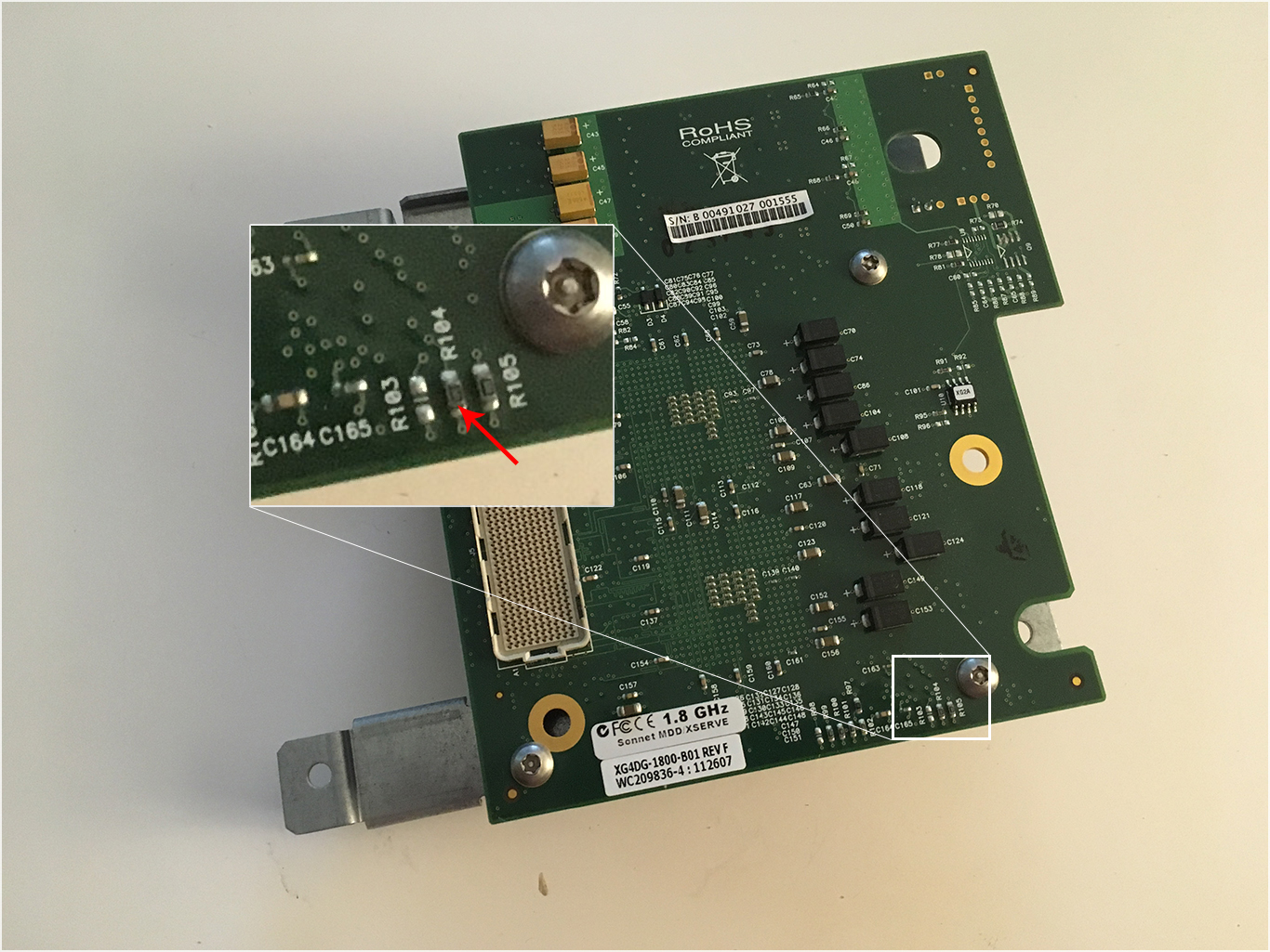
Overclocking the Sonnet Duet 1.8GHz (MDD/X-Serve 167MHz bus model)
Why would you want to mess with such a rare and expensive aftermarket card? Because why not! It’s very easy as all it takes is removing a single resistor labeled “R104”. The result will be a Sonnet Duet 2.0GHz.