Mac Pro Pixlas Mod
Updates and new relevant information is listed at the very bottom of this article.
Latest update added on September 8th, 2020.
Parts you need:
– A graphics card of choice
– Open-end to dual 8 (6+2) pin cable
• Get the cable from Kareon Kables here (link updated on July 25, 2020)
(Ships from the USA, allows for cable length and color selections. 30″ sleeved recommended)
• Or get the cable from ModDIY here
(Ships from Hong Kong, allows for cable length and color selections.)
– Quick splice taps
Tools you need:
– Screwdriver with flexible extension
– Phillips screw bit (PH1)
– Hex screw bit (2.5)
– Knife to cut wire insulation
– Crimper
– Compressed air (if you want to give your Mac a good cleaning while you’re at it)
– WD40 (optional but cleans really well)
– Multimeter (recommended)
I also put a Kit together which can be found here:
As an Amazon Associate, I earn from qualifying purchases.
Components that have to be removed (in order):
– Optical drive bay
– All PCI cards
– All hard drive sleds
– Power supply
– PCI fan (optional but will make the job much easier)
Resources:
– This blog post 🙂
– Facebook Mac Pro communities
– Macrumors forum
Why is this called the “Pixlas Mod”:
The guy that first came up with the idea for this mod, named Andree, has a website, pixla.ch. Maybe he first wrote about the mod on his blog or something (I can’t find it if he did) thus the name “Pixla’s Mod” which turned into “Pixlas Mod” because people are too lazy to type an ‘ I guess.
I’m sure there are other options for tools and taps, these are simply the ones I decided to go with. I’ve read that the Posi-Tap is a popular choice for this mod as well. The screw bits, flexible extension and screwdriver I used are all in this iFixit toolkit.
Let’s dive right in! I have tried this mod with the Mac standing up and with the Mac laying flat on a table. Having the Mac laying down makes things much much easier. I made this a step-by-step that covers everything, even stuff you probably already know. This way it can be useful to everyone. All images can be enlarged by clicking on them. I recommend reading this whole guide first before starting, don’t just follow along before you know the whole process.
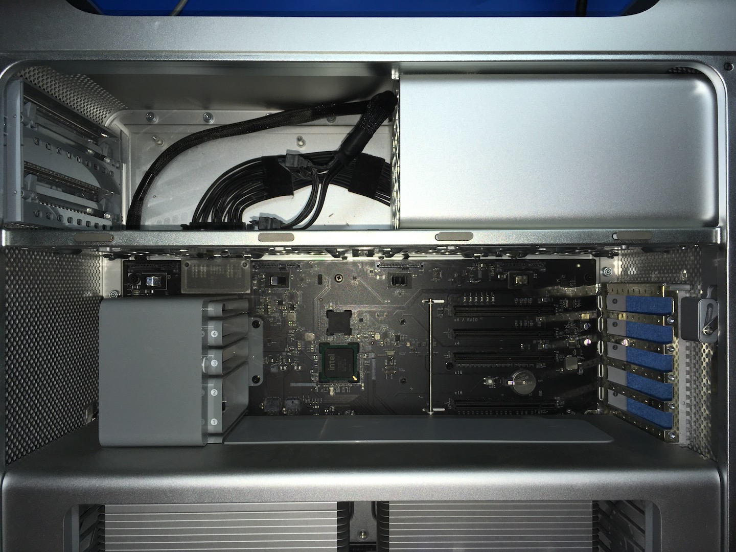
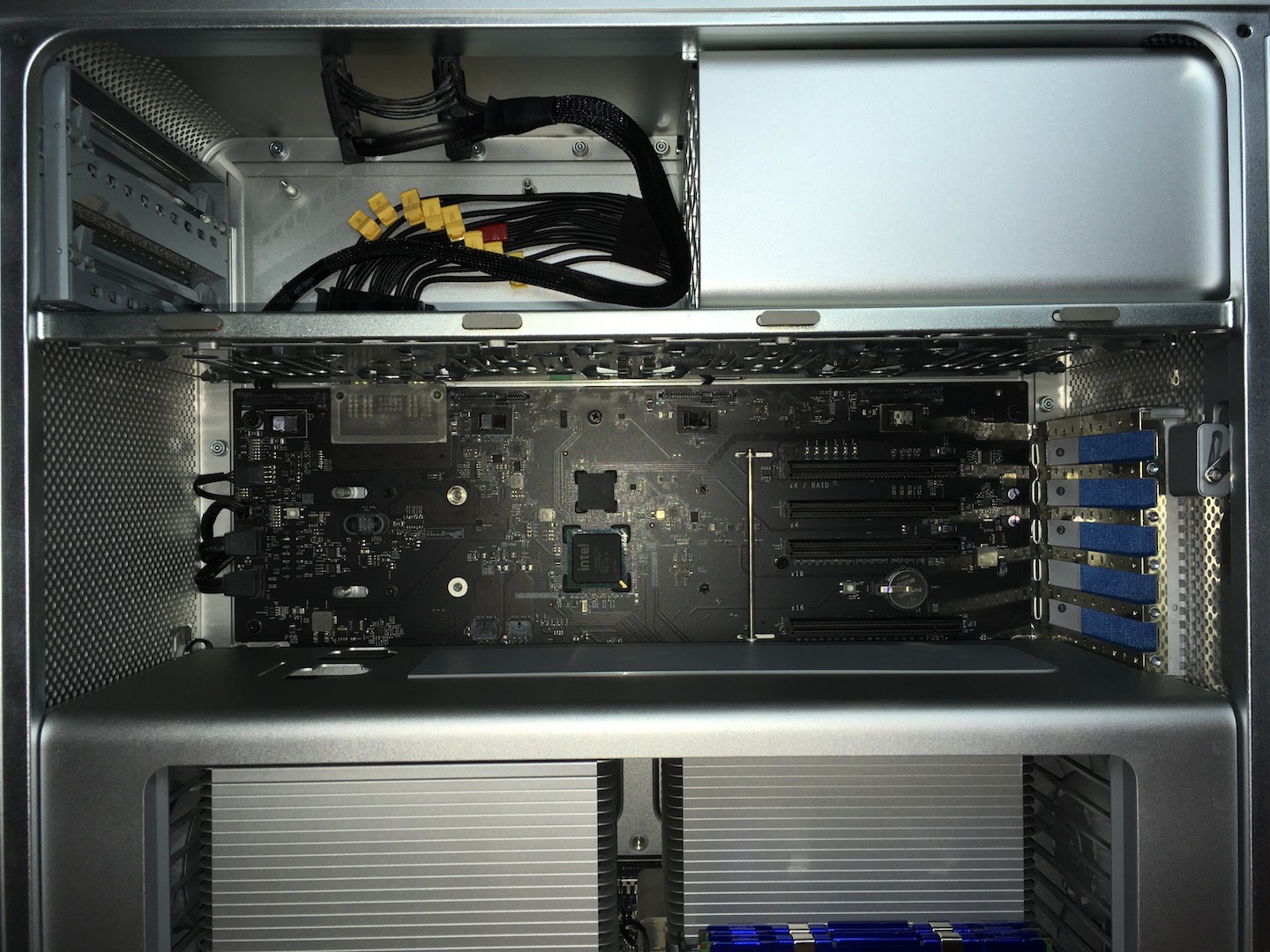
1. Take apart the Mac
Put the Mac Pro down on a towel or something soft that won’t scratch your Mac.
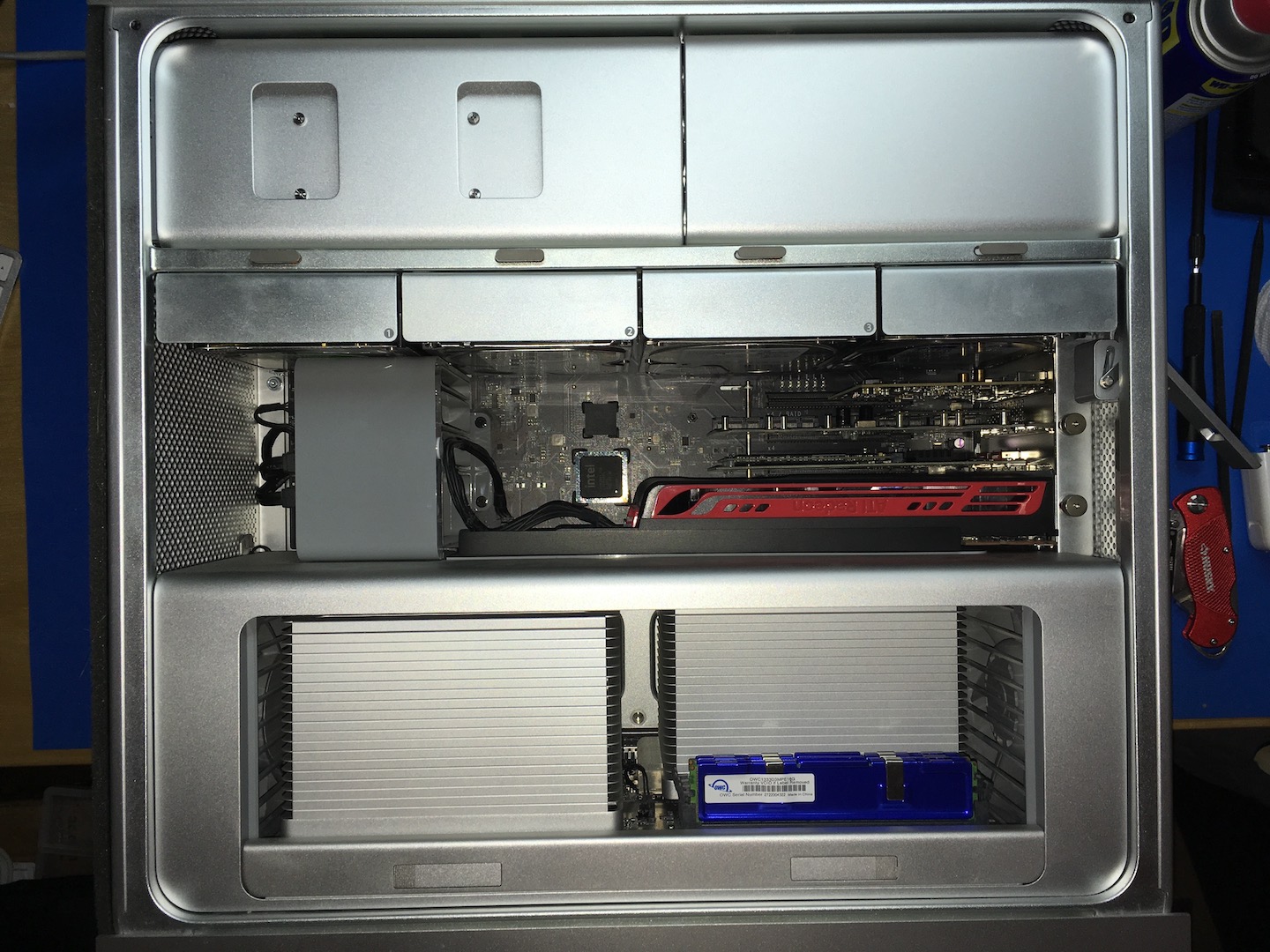
Start by removing the PCI cards, all hard drive sleds, and the PCI fan. Removing the PCI fan is optional but gives you a bit more space to work with later. Then take out the optical drive bay.
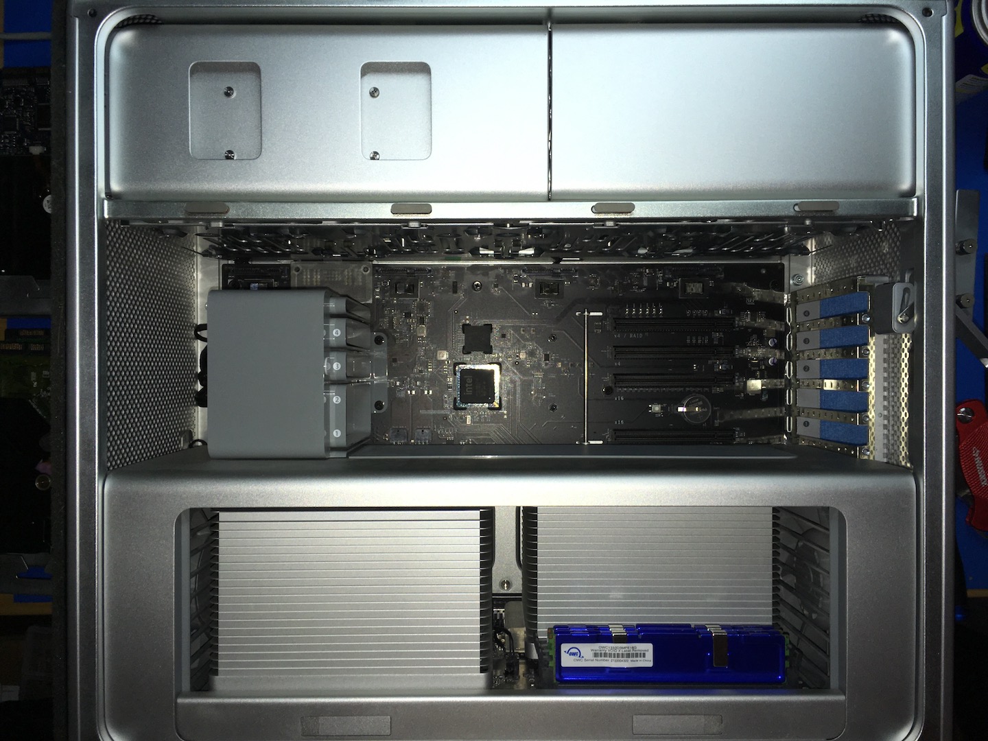
Once the optical drive bay is out, proceed by removing the aluminum back plate.
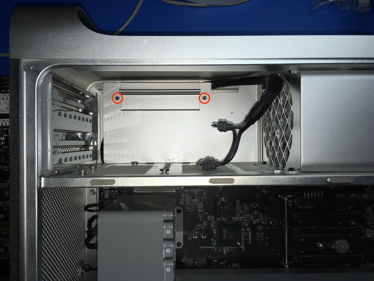
At this point, you may want to get rid of the dust bunnies in there and do some cleaning. Next up is the power supply. This is held in place by four hex screws above HDD bay 4.
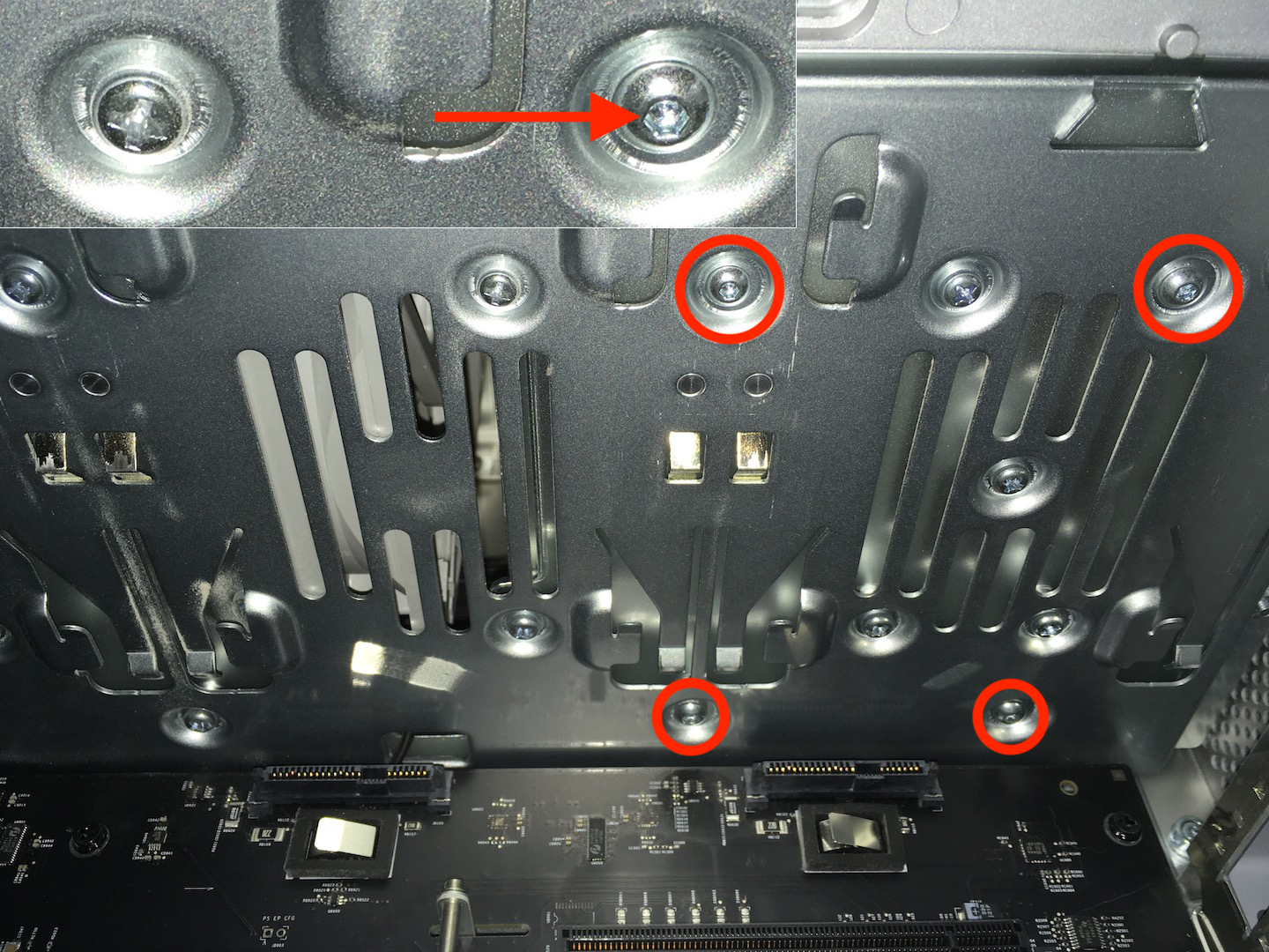
This is where the flexible screwdriver extension comes in really handy. You don’t want to be clunking around in there trying to get this done with a screwdriver that barely fits, the risk of slipping and damaging the board is just not worth it.

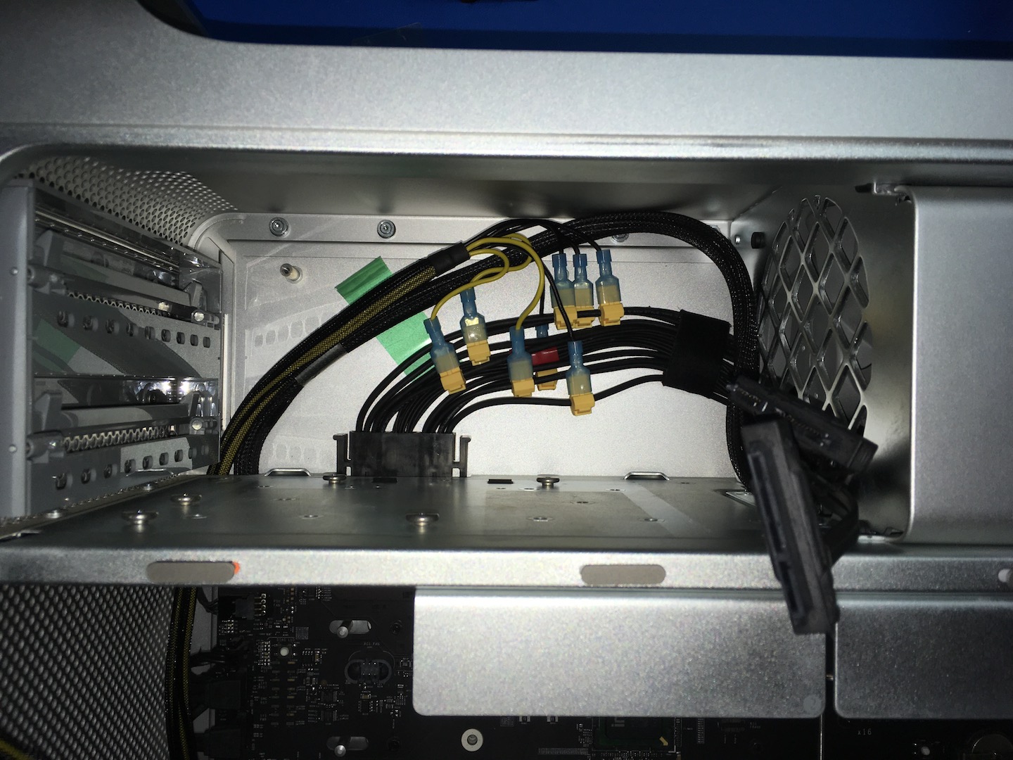
With the 4 screws out, disconnect the power supply from the board.
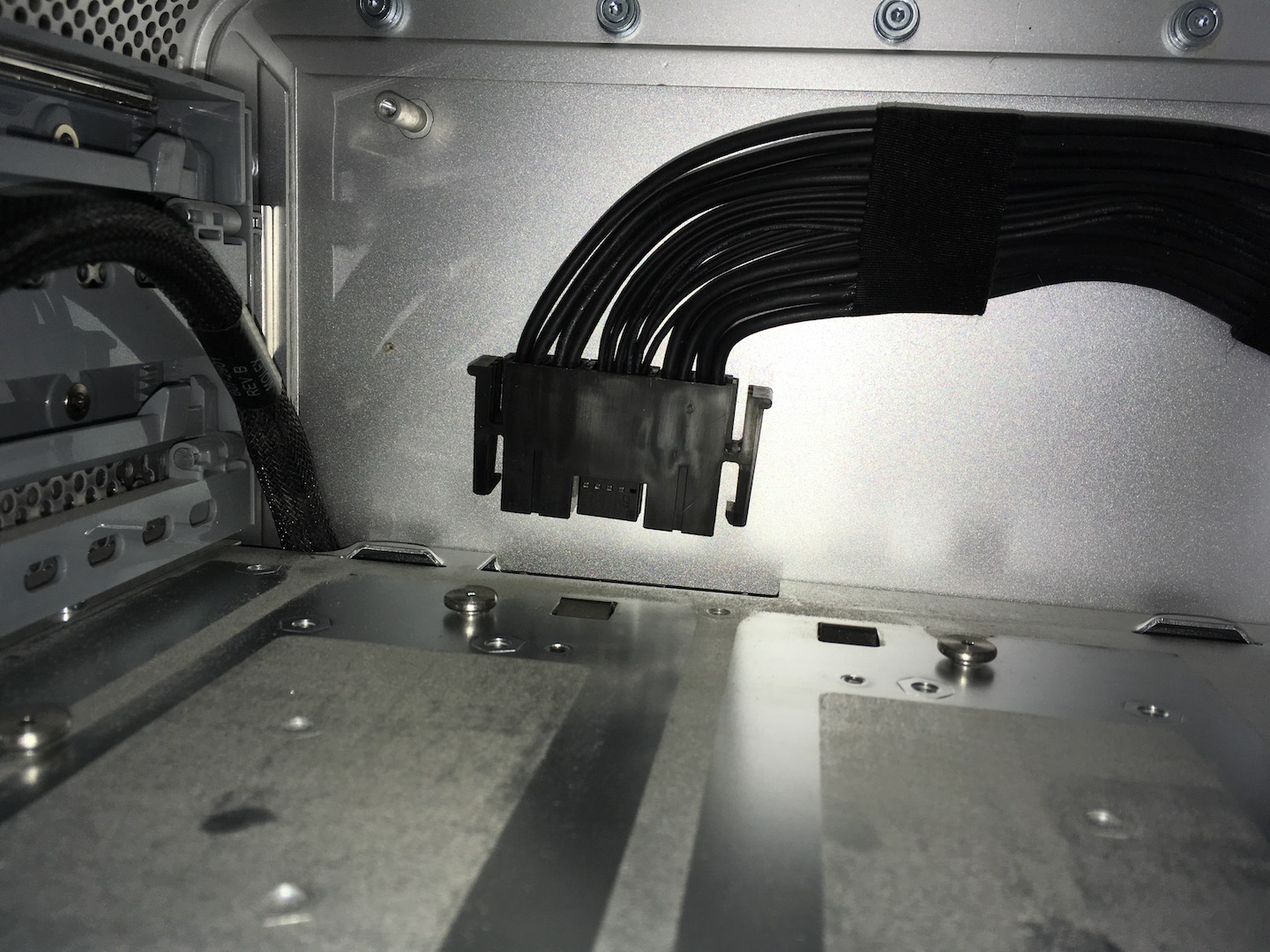
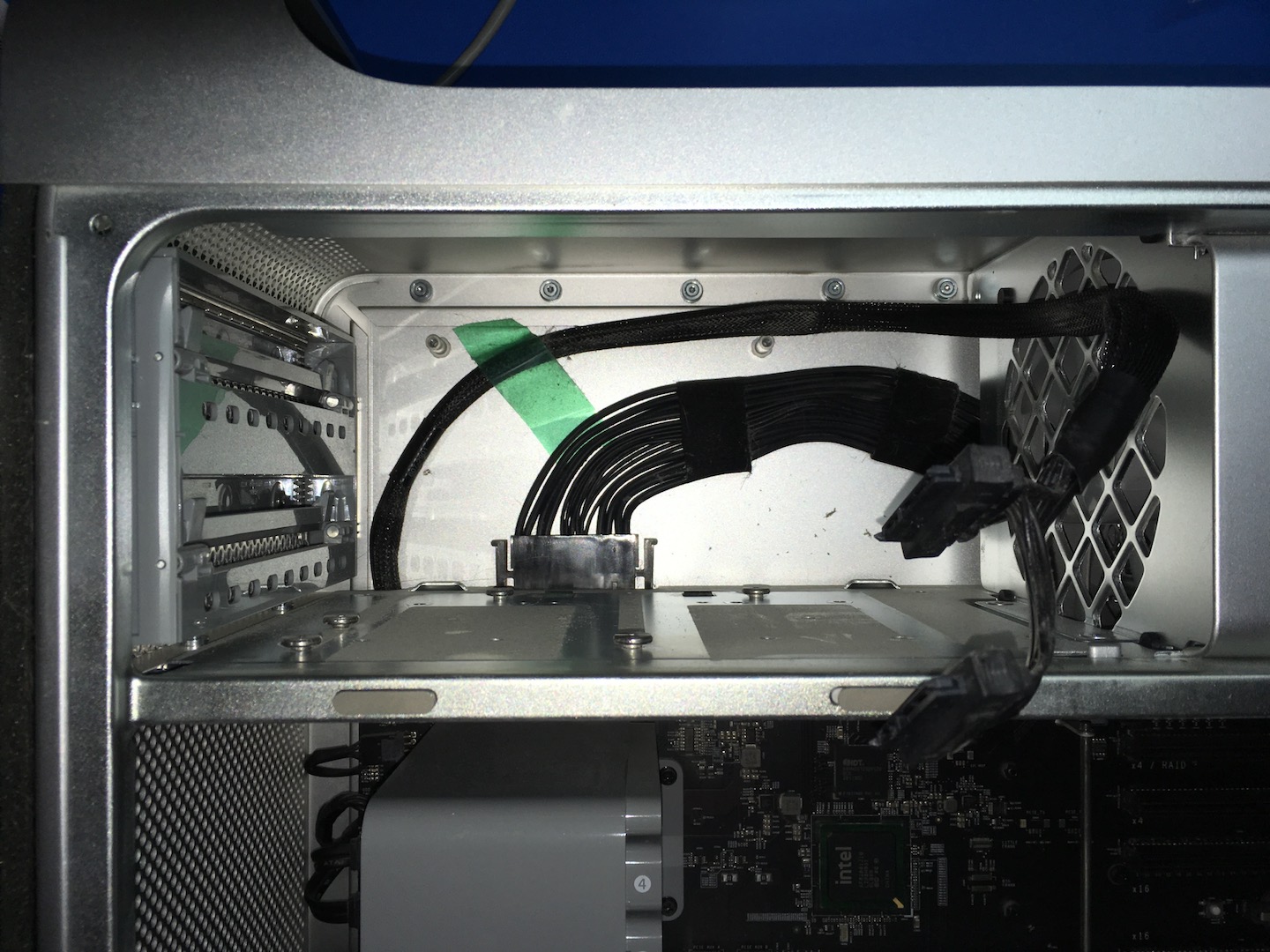
Now slide the power supply to the left slightly so that you can reach in and lift it out of the frame. As you lift the power supply, feed the cable through the hole to the other side of the fan.

That’s it. For now, the power supply is all you need, put everything else to the side so you have space to work. Depending on your level of OCD modding the power supply can take 15 minutes or an hour so make sure you’re comfortable 🙂
2. Modding the power supply
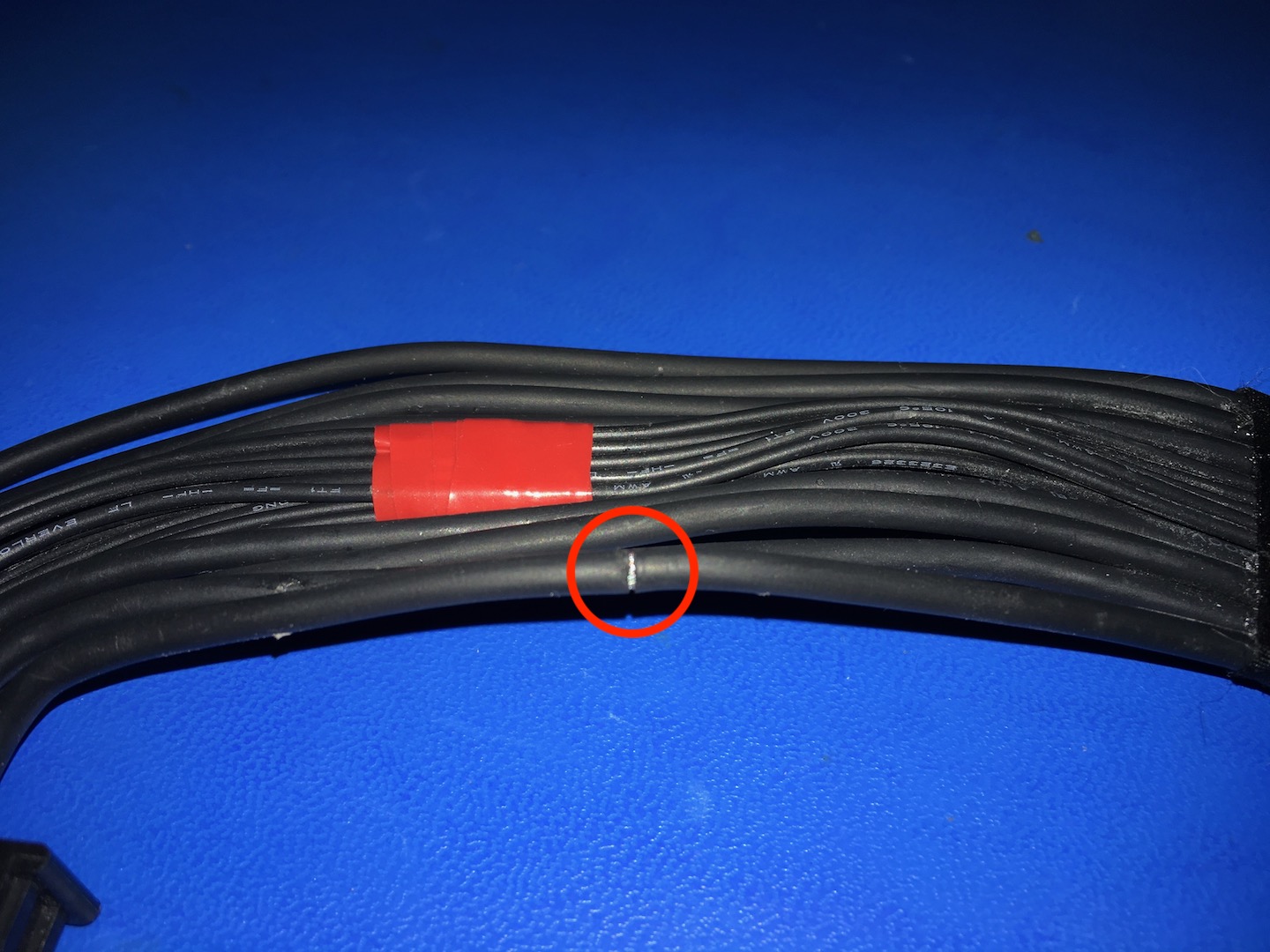
This is the fun part! But before you can start snapping on the taps, some preparations need to be made.
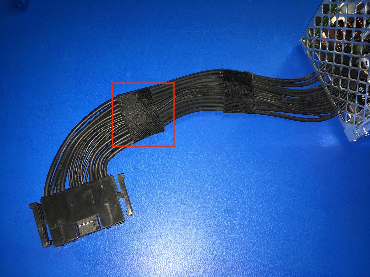
The strip of tape has to come off.
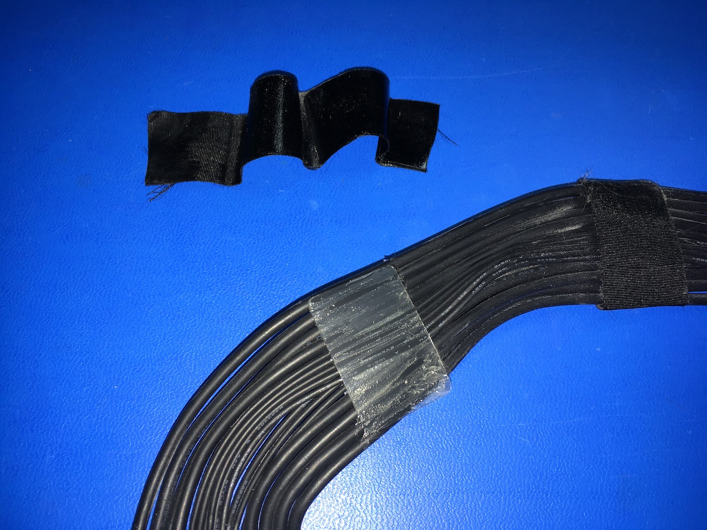
You’ll notice plastic tabs on both sides of the cable that Apple used to keep the cable nice and flat, these have to come off as well. There is a 3rd plastic tab, hidden between the smaller cables, I prefer to leave that one in place.
These smaller cables are not fragile but I see no reason to have them loose and potentially pinched once everything is reassembled. So I leave the plastic tab in there and tape it off with some standard electrical tape.

Now the worst part about this mod, cleaning the sticky tape residue off the cables. I find that just scraping it off with some tweezers gets the job done and leaves you with 90% clean cables. This is pretty time-consuming though so your approach depends on how impatient you are. With the gunk removed, a quick wipe down with a paper towel with some WD40 on it has them at a level I am happy with. If you decide to take the same approach make sure no WD40 enters the connector and dry off all traces with paper towels thoroughly.
The tape serves a dual purpose. First, it will keep the smaller cables in place, and second, it marks the cutoff height for the taps. Ideally, you want all the taps in the green area.
This is for the taps I used and link to in this article and the Posi-taps as well. Because they stick straight up instead of lying flat, going past the tape border might get you in a jam when you try to put the aluminum plate back in the ODD bay. Here’s an example of that:
This was my first Pixlas mod and the taps ended up covering one of the screw posts for the ODD backplate. Took a lot of work to get it all to fit. Thanks to this experience I now stay in the green area I show in the previous image. When you see the end result you can compare and clearly see why it’s a better option.
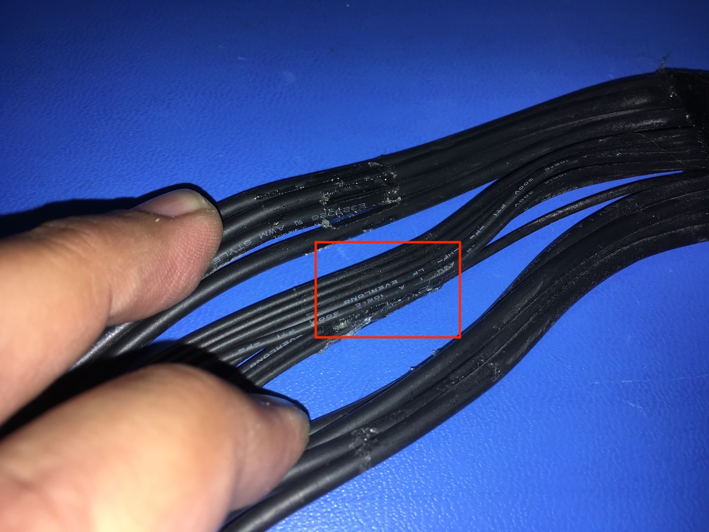
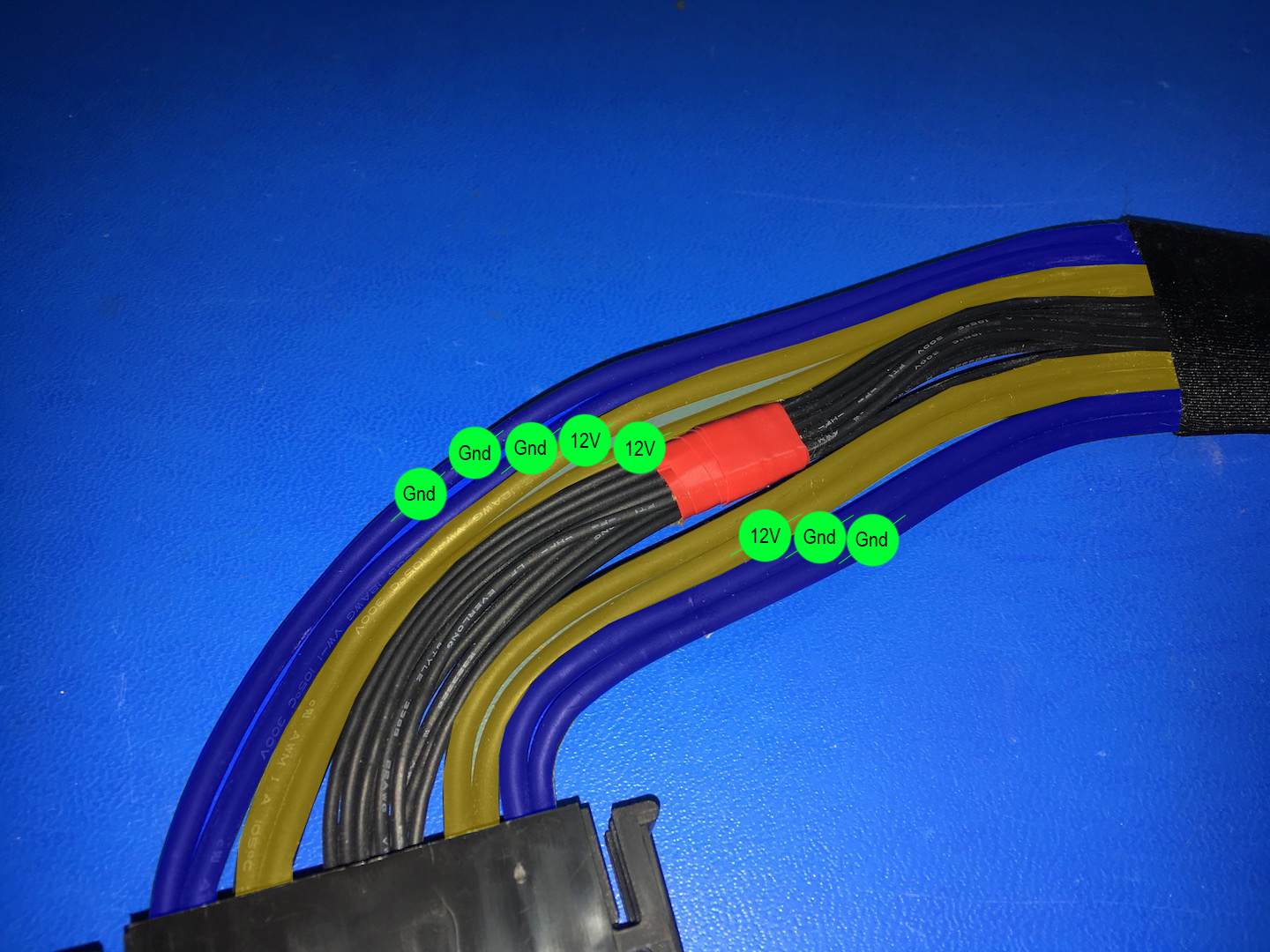
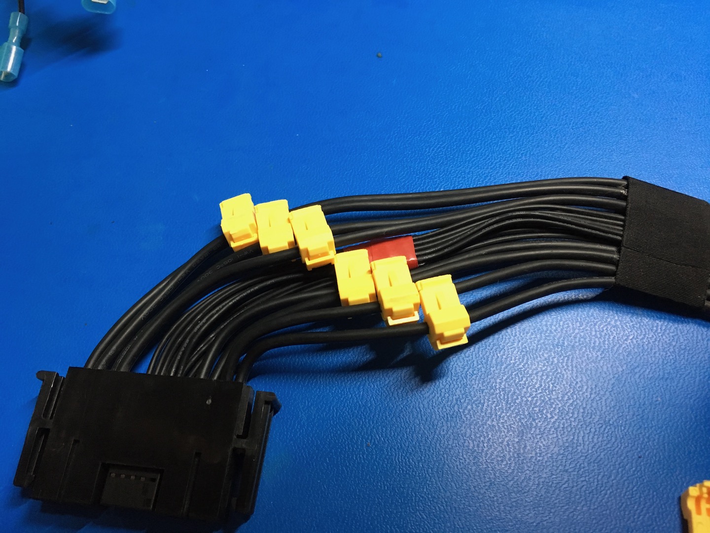
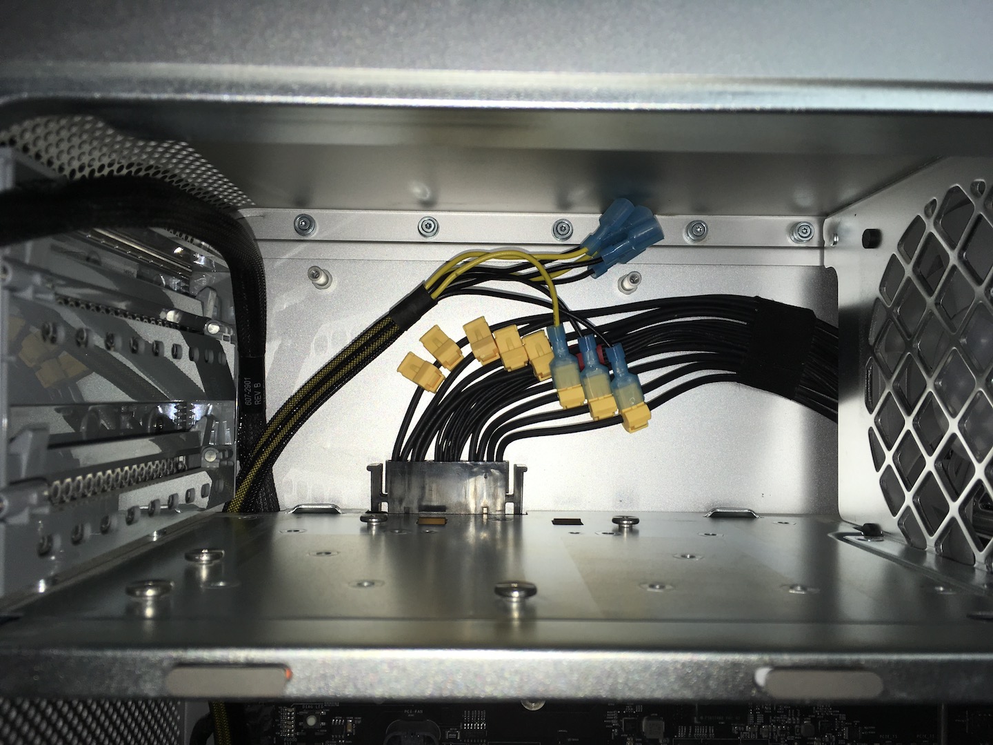
The PCI cable I used and linked to at the top of this article will have 8 wires.
3 x 12V (yellow)
5 x Ground (black)
The power supply has 4 x 12V and 4 x Ground, so one of the ground wires will end up with two taps on it and one 12V wire will be unused.
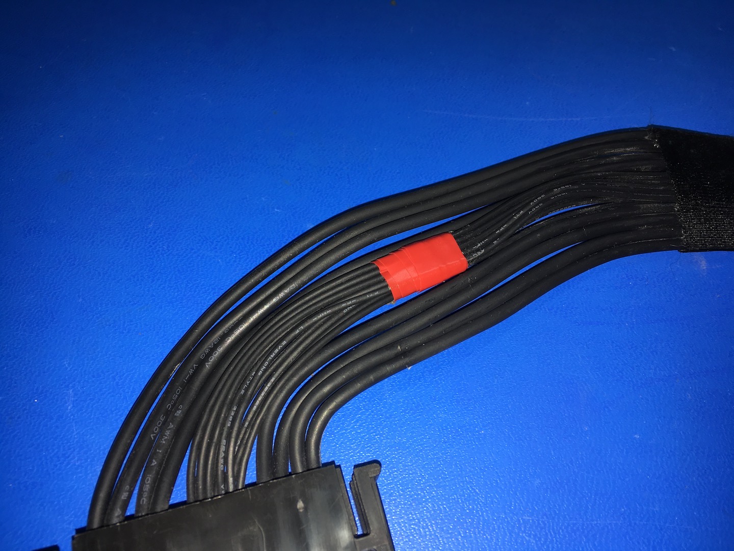
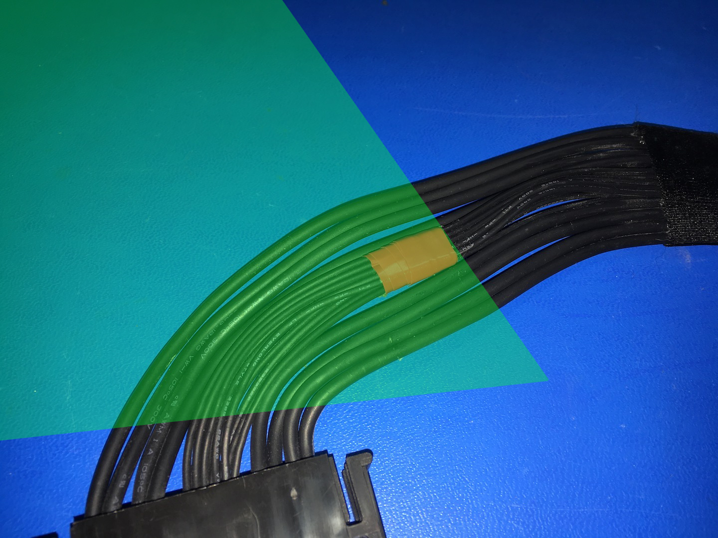
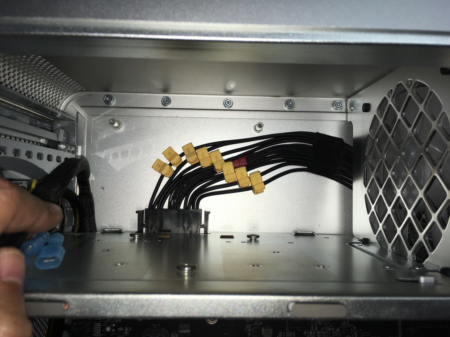
The cables on the power supply you need are these:
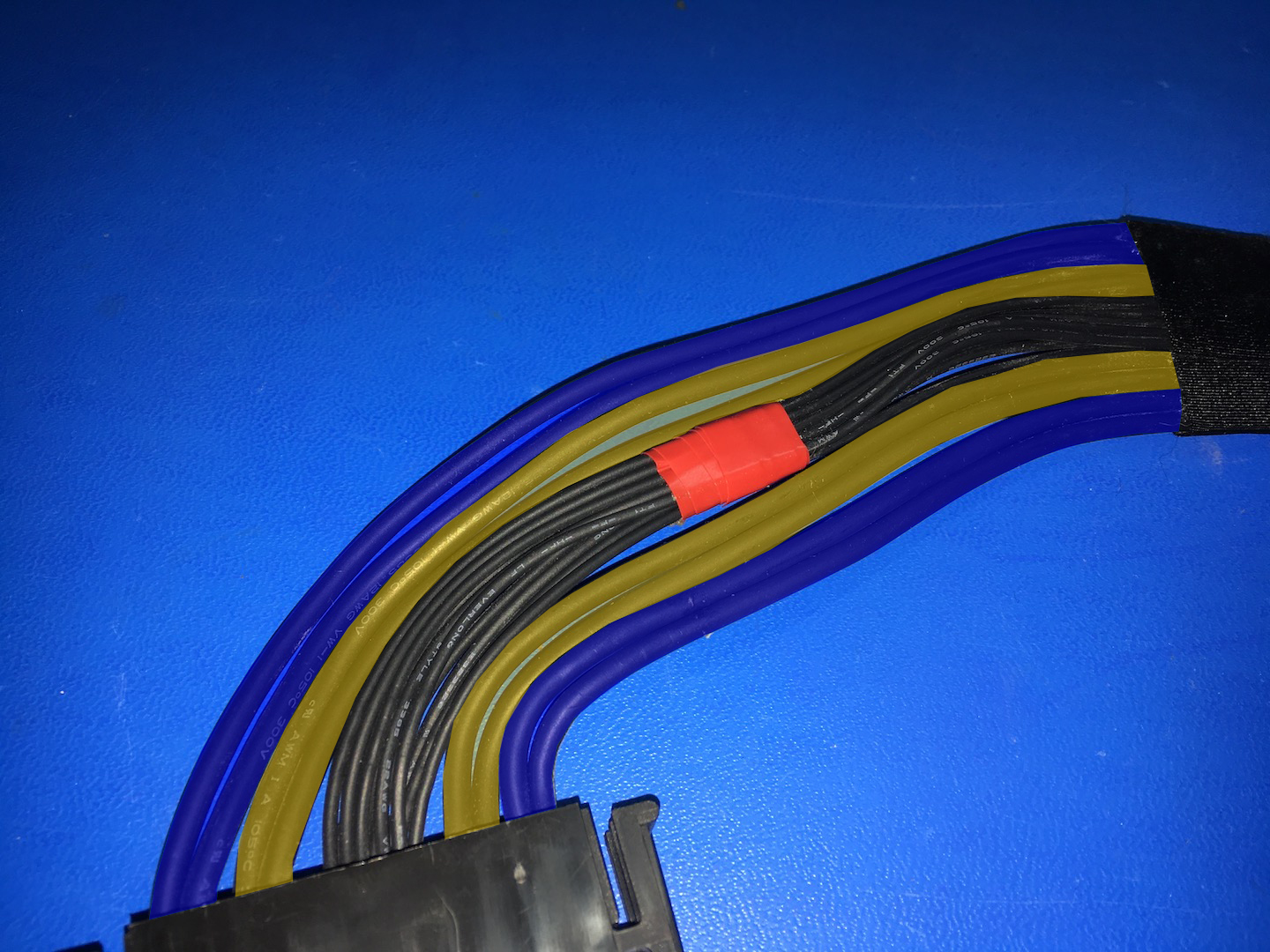
The two thick outer cables on both sides (marked in blue) are Ground.
The two thick inner cables on both sides (marked in yellow) are 12V.
== FOR THE MAC PRO 1,1 – 3,1 USERS THAT WANT TO TRY PIXLAS MOD: ==
These are the cable options for the 1,1 – 3,1 Mac Pro’s. Thank you to Mika Kilpinen on Facebook for the photo! This is where the multimeter comes in as I have not personally tested these cables unlike the ones in this post for the 4,1 – 5,1 Mac Pro. According to the information I have found the marked cables are the correct ones for 12V and Ground but double-check with a multimeter to be sure.
Cables marked in blue are Ground.
Cables marked in yellow are 12V.
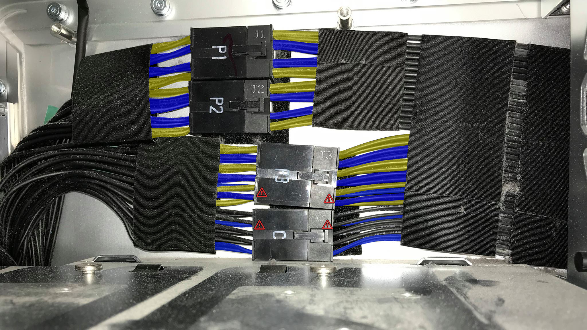
Please pay close attention to the cables marked with a warning symbol. In these locations the cables are not identical on both rows of the connector, so make sure you select the correct one. To err on the side of caution, use the P1/P2 (or J1/J2) cables as those are mirrored so the chance of tapping into the wrong cable is much smaller. Use the P3(J3) and C cables if you’re feeling adventurous.
== BACK TO THE 4,1 – 5,1 POWER SUPPLY PIXLAS MOD ==
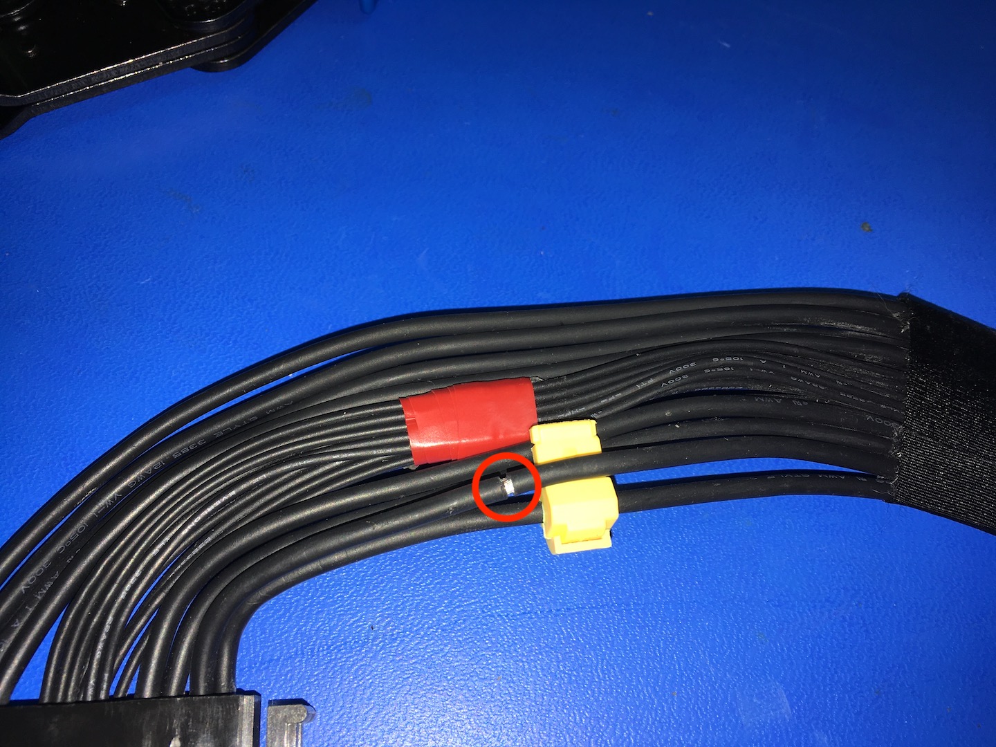
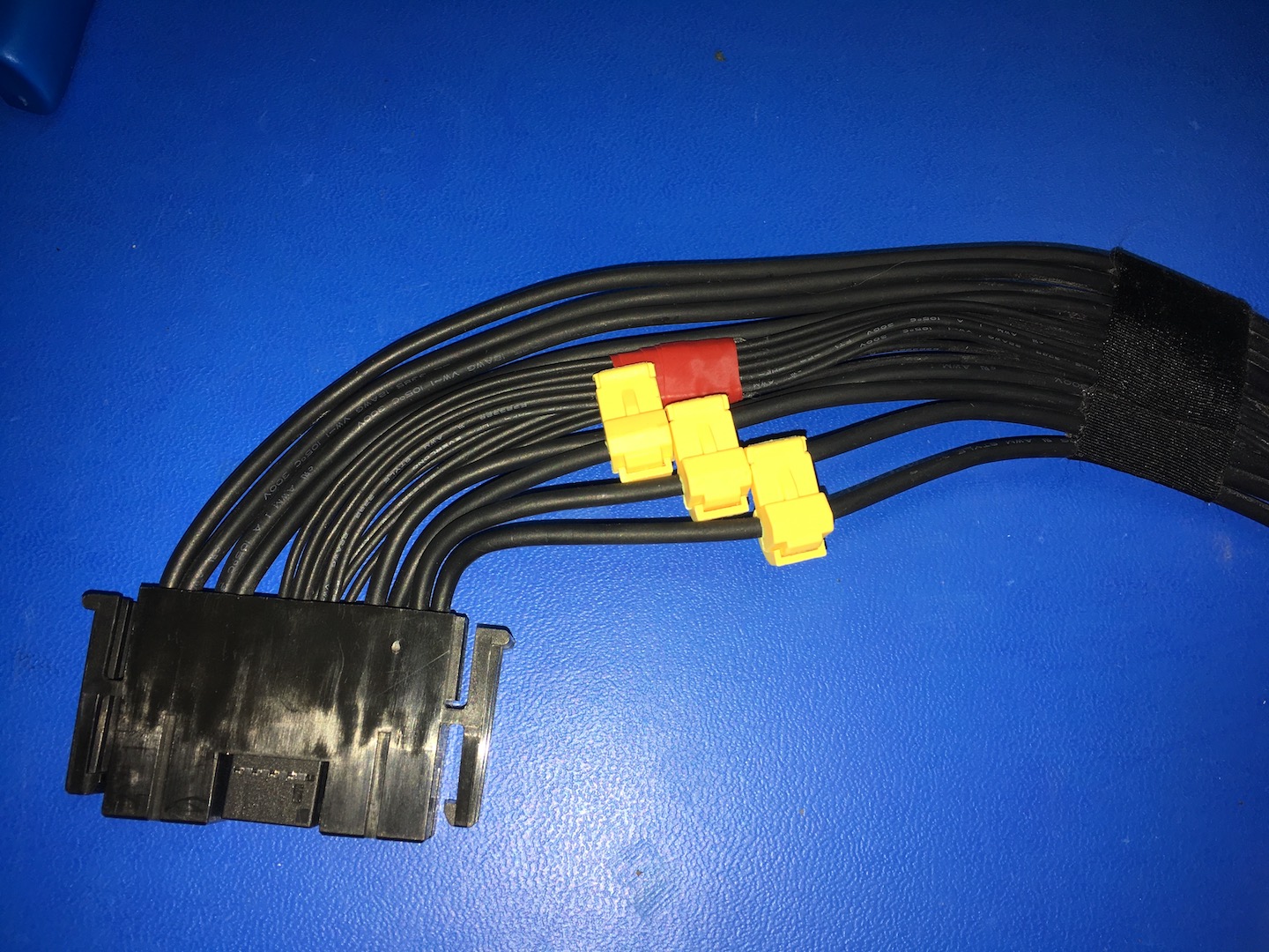
When the taps are on, this is the layout:
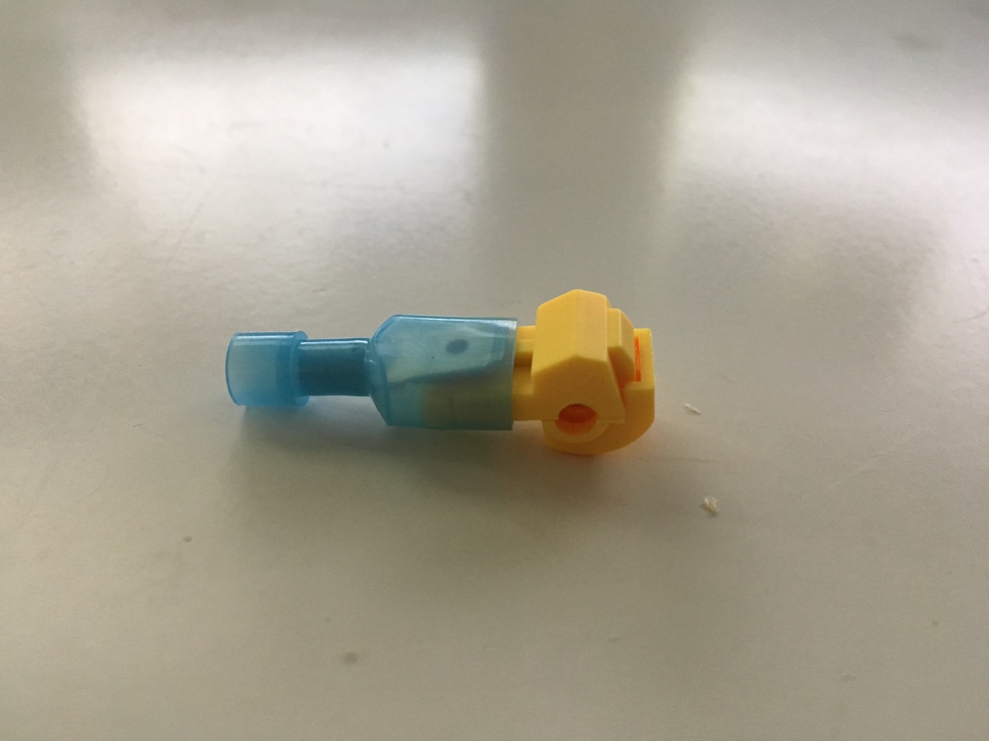
Now the cable is wrapped in a pretty sturdy black insulation. The taps (and you) will have a lot of trouble getting through it if you put them on directly. I cut the insulation all around and pull the material aside 2mm, just enough for the tap to fit in there.
Place the tap and lay the cable in place. Make sure the tap points the right way (up) and then clamp that sucker into place. This can not be done with bare hands, you’ll need pliers or anything that lets you put the amount of force needed. If it pops open after the first attempt, just close the tap and try again. If it does pop open, at least it’ll give you a chance to inspect and make sure the cable got in there nice and tight.
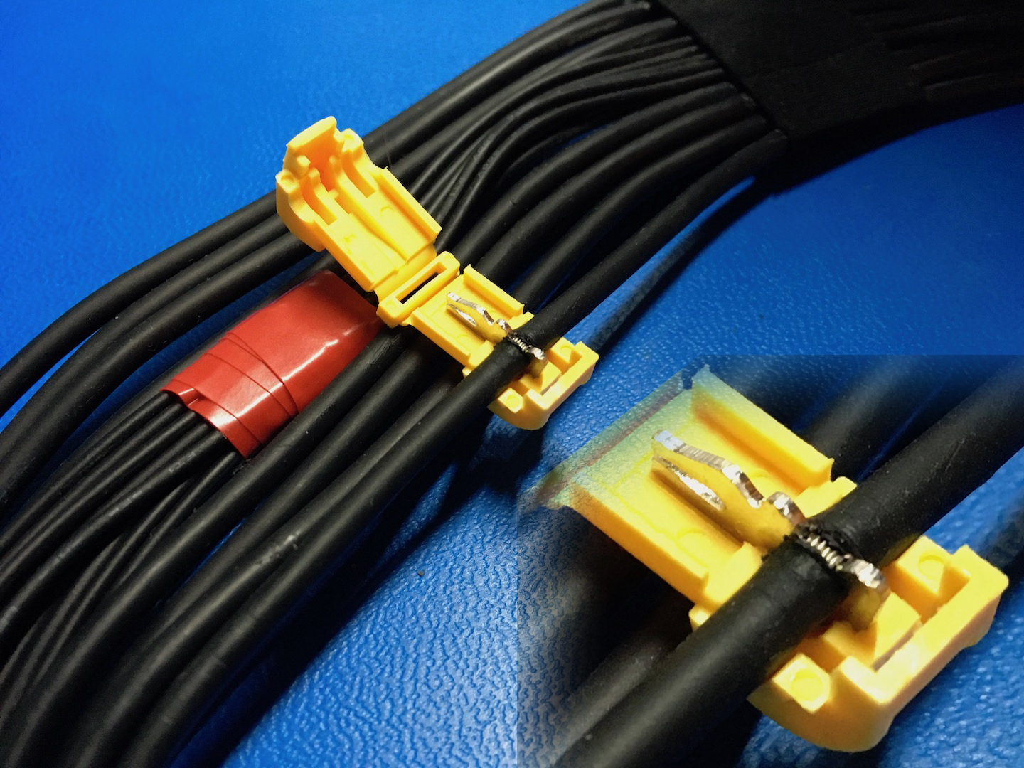
Take your time, no need to rush through it. Once the tap is closed properly you’ll know.

Then move on to the next cable.
And the next.

You get the idea 🙂 Try not to have any of the taps overlap, you want them side by side so everything can lay nice and flat when you reassemble.
The last cable will require two taps.


The power supply is ready! Give all taps a final check, try to open them with your hands (if they pop open, it wasn’t closed properly) and if everything is solid, put the power supply back in the Mac.
Did you like this content? |
|

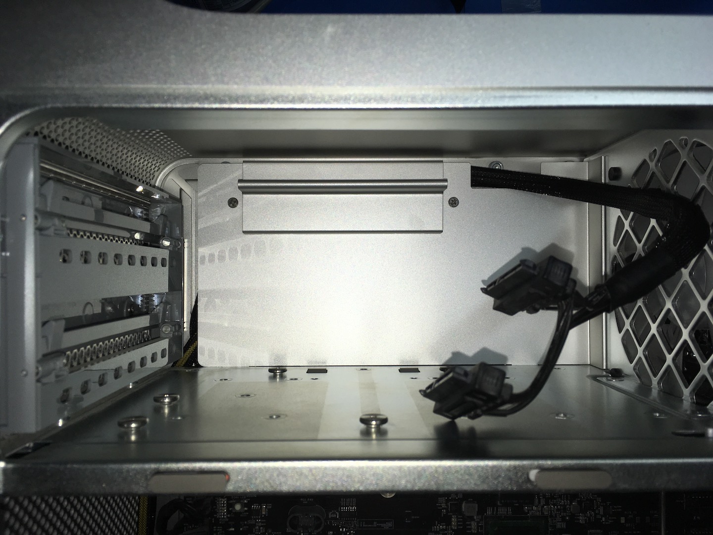
Guide the cable underneath the fan as you lower the power supply back into place. If you feel too much resistance or the cable simply won’t go through, take it slow and take your time.

If all the taps lay side by side, the cable should be flat enough to fit through the slot quite easily. Once it sits in place, screw the power supply back into place.
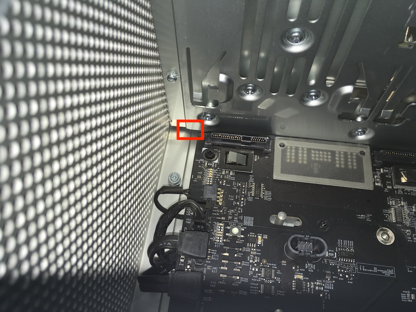
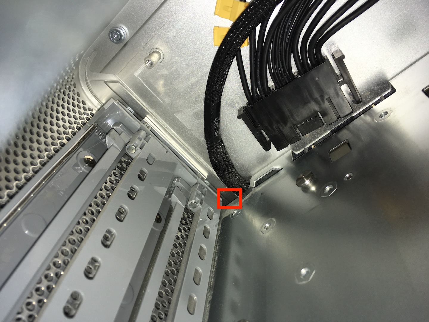
Don’t connect the power supply back to the board just yet. First, you need to get the PCI cable in place. This is done by feeding it through a small space right next to the optical drive SATA cable. Feed it in from the bottom.
To make this easier, put some tape over the PCI cable so you’re not dealing with 8 individual wires. Then feed it out the top.
Now it’s time to prep the PCI cable. It comes pre-cut so all you have to do is slide off the insulation. I found it to be a better fit if I strip double that amount of cable though so I can fold it over. Now I forgot to take pictures of this so to demonstrate here is an amazing graphic:
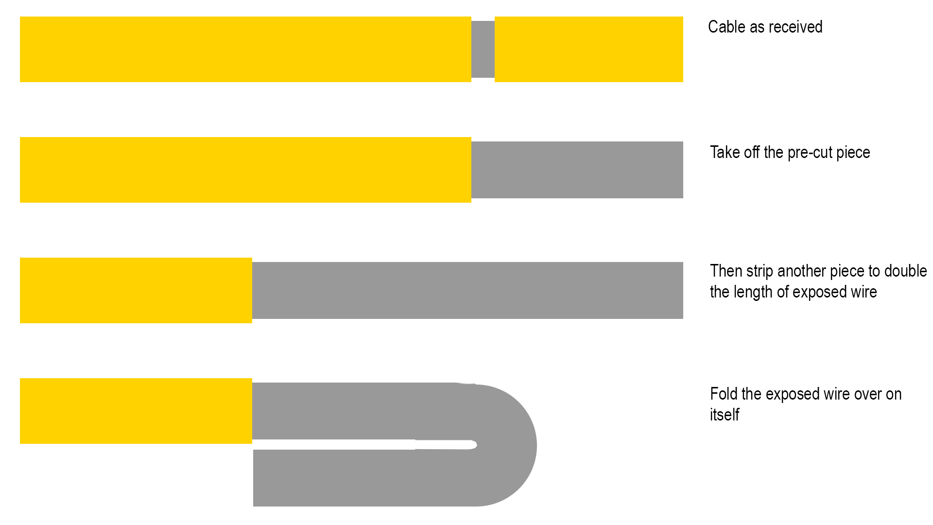
This will ensure a snug fit into the spade connector. Put the spade connectors on all the cables and use a crimper to make sure it’s permanently on there. Once all the connectors are in place, pull the cable down to give yourself space to work and hang the optical drive cable to the side for now.
Time to start connecting! Use the diagram above to see which cable goes where. Take your time and make sure the connectors snap into the tap firmly. The spade connectors may fold to one side rather than clip into the tap, check both sides of the tap to make sure the spade went IN to the tap and not off to the side.
Example of what you should NOT be seeing:
And what you SHOULD see on both sides: no metal spade:
Route the cables so that they are loose. Loop it around, weave it through, whatever gives you a smooth connection. If cables are tight, find another path to connect them.

The result should look something like this. Both screw posts for the backplate are unobstructed, all taps side by side and the optical drive SATA cable routed along the top. Now see if the backplate fits. Don’t force it into place, it will bend and the cables behind it will have a lot of pressure on them. Take the plate out and rearrange cables as needed to make it fit comfortably. If in the end it just won’t fit… leave the plate out, you don’t really need it anyway.
You should have plenty of cable left to route it along the edge of the board, across the intake fan, and to the GPU.

If you’re happy with the result, put the optical drives bay back and start reassembling your Mac Pro.
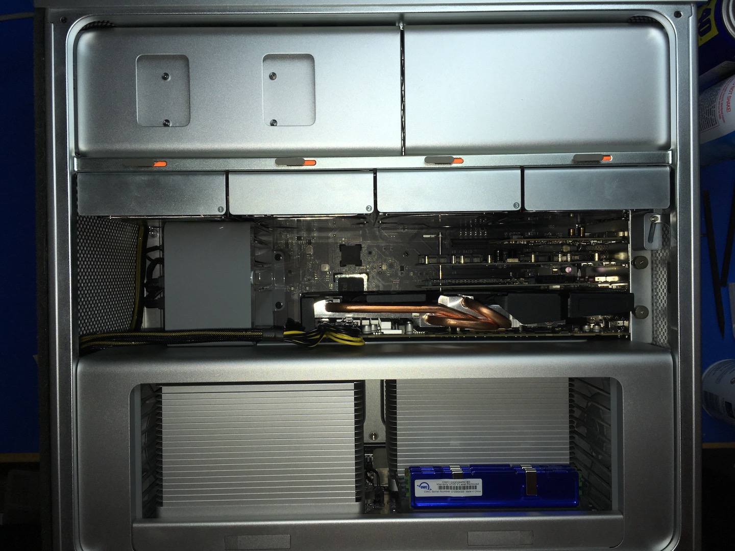

YOU’RE DONE! If you did this mod to facilitate a bad-ass GPU, start ripping benchmarks and getting some work/gaming done 🙂
Why?
Q: Why did you not cover testing the cable with a multimeter?
A: Because the power supply cables were stripped before placing the tap, I am confident in a solid metal-to-metal connection. Measuring output with a multimeter is just to make sure power is flowing through and the tap was not obstructed by cable insulation. I do recommend using a multimeter if you’re doing the Pixlas Mod on a 1,1 – 3,1 Power Supply to verify my image did indeed mark the correct cables.
Q: What are other ways to get this mod done?
A: Instead of using taps, you could take apart the power supply and solder the PCI wires directly into it. Apart from being a fun project, I do not see clear benefits using that method and the PCI cable I linked to here will be too short so another solution will have to be found/created.
This was put together pretty quickly, I might add more information to this page in the future. All relevant information is already here though.
If after all this you still prefer someone else do the mod for you, I’m happy to help.
Updates:
May 23, 2018 – Added image with 12V and Ground color-coded cables for the Mac Pro 1,1 – 3,1 power supply.
December 24, 2018 – Hrutkay Mods has made a video-based loosely on this guide, you can find it here. He intended to follow the guide step by step but had to go in a different direction; soldering instead of splicing. If you want to take the soldering route, do check out the video.
March 24, 2019 – I have made a video about the Pixlas Mod as well that follows this guide. You can find it right here.
June 25, 2019 – The Mac Attack did a video on the Pixlas Mod as well, it turned out really nice! Go check it out here.
August 5, 2019 – Pixlas Mod, is it really needed?
June 24, 2020 – Due to the shipping delays with COVID madness going on, I have found a new cable supplier that makes and ships from the US. You can have a look at their cable review here.
September 8, 2020 – ModDIY has reached out and asked for some corrections to be made.
– Cables are shipped from their warehouse in Hong Kong, not China.
– COVID-19 related shipping delays have been resolved, cables should now arrive in about a week to the US.
– Lengths available from 30cm – 80cm
– Another exclusive offer for readers of this blog: different cable sleeving is now available upon request. Different colors do not affect the price! Just leave a note in the Order Instructions during checkout to pick your color.
Did you like this content? |
|
128 thoughts on “Mac Pro Pixlas Mod”
Great post! Very Hard to find this type of information lately. Not sure why. I do have several questions but want to re-read first before asking something really stupid. Appreciate it.
Great Mod, i will try it on my Mac Pro, just a dumb question, is the power output on the resulting 6 pin is 75w?
Output is what the card asks of it. Even if the GPU asks more than 75W the PSU will easily be able to supply it, unlike the 6-pin connector on the board. Power isn’t pushed by the PSU, it’s pulled by the components 🙂
El pci son 75w + un el conector auxiliar A que son 75w y después el conector auxiliar B son 75w, por lo que e estado mirando en Internet si lo suma los tres te da un total máximo de 225W
Hey, I notice that the fourth larger wire—on the right side—has no clamp around it. How come that wire is left alone?
Only three 12V wires are needed and the PSU offers four, so one will have nothing to do 🙂
This is great. Just a minor thought … for cleaning adhesive gunk off the cables (or anything else), the ideal product is rubber cement thinner. This is sold at graphic arts shops as Bestine. There are products at the hardware store that are similar. This stuff is much more effective and less messy than wd-40, which adds gunk of its own. Just use with decent ventilation
Even better still is Eucalyptus Oil or Tea Tree oil.
It’s a natural product that does wonders with removing any type of adhesive residue from tape – especially gaff tape!
Thanks for the guide – went like a charm, but I am stuck. All blades are seated, wires were prepped with a gap for the taps, multimeter shows 12.46v at each +, but the dual EVGA NVidia 1080ticards are still not being recognized by the system. This was my first time doing this mod, but I think I got it all. Machine boots up without issue, just doesn’t see the cards as if there wasn’t power at the 8-pin connector.What could I have missed?
This mod was for an AMD Radeon video card, (as to my thoughts) like the Vega VII. Apple really isn’t supporting Nvidia cards with Mojave (from my knowledge)
You need to download the 1080 card drivers from Nvidea using the links available on the MacVideoCards.com.
these drivers are OS build specific.
Thanks for the guide!
Will this provide enough power for:
#1) 1080ti/Titan-xp
#2) Vega64
Hi Ben,
As long as their power draw is less than what the PSU can provide, Pixlas Mod will handle it just fine 🙂
Great write up, thank you for taking the time to figure it all out and share. I just performed this yesterday successfully and I am not running a Radeon Frontier Edition and playing Fortnite with upwards of 100fps/
Very nice! Glad the guide was useful to you 🙂
Thank you for the clear instructions. I modded my cMP now as well. Because of a VEGA 64 I had to take out the front fan assembly and hooked up a standard 12V fan to the now obsolete PCIe 6-pin connectors. It’s too loud, so after Christmas I will be getting a silent one.
Hi, great post. Any preference on where to connect each 12v and ground, would it matter if the right side ground have the tree ground cables connected instead of to the left side ground?
Is it known what right and left side 12v supplies? Maybe one for each CPU?
Thanks !
Tks a lot, perfect.
Awesome guide! I followed it to the letter and my 4,1 fired right up as did the GPU. So much better than risking overload on the mini pci connectors.
Thanks for sharing the success story Daniel! Which card did you squeeze in there?
Thank you for this, it’s certainly very interesting and I’m definitely considering sinking my teeth in.
Do you know how well this would work with an Aorus 1080ti xtreme that needs two 8-pin pcie?
I currently have it set up with two mini pcie into 8pin and two SATA bays into one 8pin.
I’m not super technical as I approach animation from a design background so all information is greatly welcomed.
Thank you,
Jai
Oh yeah the Pixlas Mod can easily handle 2×8-pin for that card. At most that card will use 330-380 Watts and your power supply can provide 980 Watts total. Plenty of power to spare even if you have the highest end CPU’s installed 🙂
Can i use 2 gtx 680 inside macpro. I will power one using pixlas mod . And the other from the motherboard. Any suggestions?
If that card has 1×6 and 1×8 pin, you can power both 6-pin ports from the board and both 8-pin ports from Pixlas
Hi, Jay. Step-by-step guide, along with your video companion on YouTube. I
now feel pretry confident I can do this on my Mac Pro 3,1. Any confirmation
or update on the cable layout for the Mac Pro 3,1 PSU? I don’t mind getting a multimeter to be sure, but if anybody has confirmed it is as on the photo you added then it will make it easier. Would you consider making a bideo update for the 3,1 PSU case?
Thanks!
I don’t have a pinout for the 3,1 PSU so the 3rd party information I used in the past is all I have. No 3,1 in my collection either to test this unfortunately. If you can confirm with a multimeter that would be great 🙂
Hi I’m about to do the Pixlas mod when making the incision for the PSU should I be only making an incision on one side of the wire? Or should I be making an incision all the way around? Hope this makes sense, thanks!
Hi, the incision goes all the way around. Good luck!
Awesome and easy to follow guide. Took me about an hour to do it and looks pretty much exactly how your’s did. I recommend anyone with a Classic Mac Pro do this mod so you can get more life out of your machine.
As I am from Germany: where else could I get this 70 cm 2 x 8 pin cable? Tried everything: Ebay, Amazon, Auntie Google …
The link is for a cable that’s ordered and shipped from China, should work for you as well and they offer “Free Shipping Worldwide” 🙂
hi Jay,
is there any chance this cable can be done from some other cable? Due to covid china does not send anything out.
Another way to find PCIe auxiliary power cables with 6+2 pin connectors is to scavenge them from broken PCs or power supplies.
Can you do a double pixlas mod on one PSU? In case you would like to use two power hungry GPU. If yes, can you detail how the splice should be?
Many thanks!
Sure, as long as you don’t exceed the amount of watts your PSU has to offer. The setup would be identical, just put two cables per splice, one for each pixlas cable 🙂 The splices are heavy gauge enough to handlke 10 of them so no need to use additional splices.
Hi Jay,
I face stupid issues to get my ordered Pixlas Mod cable (Open-End to Dual 8 Pin (6+2) PCI-E Sleeved Cable (70cm + 10cm) and ask you if you know a different route for me getting this cable? I’ll pay the price wanted. I’ve ordered at Moddiy.com but two times undelivered and still no progress and thinking now about a refund. Really ridiculous for a simple postal delivery from Hong Kong to Amsterdam, The Netherlands.
Highly appreciated if you or anyone else can help in here.
Kind Regards,
Robbert van Gom
Amsterdam, The Netherlands
Hoi Robbert,
I don’t know of a source in The Netherlands but I will ask around and leave a comment here if I find something!
Groeten! 🙂
Hi Jay, I’ve managed to find myself a solution. So no worries on that part. About the double Pixlas Mod on one PSU, you advised two cables per splice. Is there a rule on the cables connecting to each other to one splice? I understand to have the Grounds combined and the 12V combined, but is there more specific in order?
Thanks for your swift response and keep up the good work!
Regards,
Robbert
Amsterdam, NETHERLANDS.
Better said:
Is there an order of connecting like expressed below considering two cables connecting to one PSU:
Example:
Cable1-12V-1 Cable2-12V-1
Cable1-12V-2 Cable2-12V-2
Cable1-12V-3 Cable2-12V-3
Cable1-Gnd-1 Cable2-Gnd-1
Cable1-Gnd-2 Cable2-Gnd-2
Cable1-Gnd-3 Cable2-Gnd-3
Cable1-Gnd-4 Cable2-Gnd-4
Cable1-Gnd-5 Cable2-Gnd-5
I know that identify the numbering would be quite a challenge, but that’s the reason of my question, knowing that we will combine;
5x Cable1-Ground with Cable2-Ground
and
3x Cable1-12V with Cable2-12V
Thanks again !
Jay,
Managed to do the “double” Pixlas Mod to one PSU. So far so good. Will hook on after a trial period a Radeon Vega 64 and Radeon RX 580 and see what happens. Got now a weaker Radeon HIS DH 7950 with a simple GT120 in the system. Play safe is the first step.
Thanks for your support.
Regards,
Robbert
Amsterdam, NETHERLANDS.
With this method can i put back the dvd player will it fit and work ?
Yes it will 🙂
Thanks so much!
Unfortunately the
01 Quick Splice Wire Terminals T-Tap-Kit Spaten Draht Stecker Set
and
02 Quick splice taps
are not available for shipping to Germany. Anybody found an alternative in Europe?!
Thx!!!
Could anyone please tell me what sort of resistance they’re seeing between 12 V and ground? I have a short, and I can’t find it for the life of me.
Hey, I liked this mod a lot. All my work became easy and took a little time.
Hi, I like this Pixal Mod and it will be fun doing it as a DIY project.
Hello thanks for the tutorial. I just wanted to confirm for you that the 1,1 to 3,1 information you provided, but were not sure on the authenticity of seems to be accurate. I have just finished the Pixlas mod on one of my 3,1’s with a GeForce GTX 680 Classified 4GB. I tapped into the cables from the P1 and P2 power connectors and I also confirmed voltages with my multimeter. I am doing my other 3,1 soon as I use one for MacOS and the other for Windows 10. Thanks again for your efforts with this tutorial.
Awesome Josh, thanks for confirming the pinout!
Quick question: I just ordered the cables, so have some time to get the quick splice taps. I do plan to get the ones from 3M. They are expensive, but available locally.
Any suggestion which size I would need? Don’t want to destroy the cables with too tight ones… I planned to use the 3M Scotchlok 951. Including isolation, they are made for 3,81 mm cables… Please advice, and many thanks in advance!
(My Radon RX 64 is waiting in my 4.1)
Thanks so much for this. I just completed my first one, and it works! I thought for sure I would mess it up, but I followed your instructions carefully and did it right, it works, and I’m very happy! I’ll be doing a few more in the coming weeks. Thanks again….
Awesome! Glad to hear. Which cards are you powering?
Thank you,
successfully updated my MacPro 5.1 with Radeon Vega Red Dragon with you mod.
Much better than SATA Power Adapter.
Greetings from Germany
dvcheck
Glad to hear it helped you Ralph!
I have done everything here as instructed, but my machine will not show a picture. I have an MSI Radeon Vega 64 with a 4,1 2009 Mac Pro. It’s been firmware upgraded to a 5,1. I have the led’s showing and the fan spinning on the card, but no picture. I put back the standard ATI card and I can drive my screens and see the boot loader as normal. I am not sure what to do now, cannot think what is incorrect, I will check on all the connections. I also thought about leaving the ATI card in and checking the hardware profiler to see if both cards are recognised. I understand with this card I cannot see a boot loading screen, but should be able to see a screen when it gets to High Sierra login screen. I plan to run Mojave on this, but need to get this card running first.
Looks like it was a false alarm, however I don’t know why it wouldn’t show the login screen. Could not get it to work until I swapped it to the second 16x slot on the logic board. Then I got it show up with a direct connection to an HDMI monitor. I turned off the login screen and got the Mac Pro to boot straight in and now it’s working in slot one as it should do running off the pixlas mod. Now onto further mods, such as processor and SSD boot NVME boot drives.
Great tutorial! It worked like a charm! Almost cut one of the ground leads from the power supply in two, but managed to salvage it.
Now I’m top spec’ed: amd Vega 64, 12 cores, 32 gb ram, ssd’s, raid, usb3. And (for fan control) Mojave.
It is snappy and great. Mac Pro 5.1 FOREVER!
Nice specs! That should last you a while 😀
Will this effect the fans on the machine at all? I’ve noticed my motherboard heat-sync fans are constantly going. Was wondering if that had anything to do with the mod or if messed up the heat-sync fan connection(s) when upgrading my CPUs. Also not sure if running 2x 1080ti SCs might be affecting the fans always being on.? Any insight is welcome! Thanks again for this video! Breathed new life into my mid 2010 5,1!
Hi Rob,
The pixlas mod should not affect fan or temperature behavior in the Mac Pro. If a serious amount of juice is pulled (from anywhere in the Mac) I would expect the PSU fan to ramp up but not the CPU fans. If you don’t already use it, install a temperature monitoring app such as TGPro or Macs fan control. This can tell you why the fans are ramping up and which sensor(s) it’s responding to.
Maybe a really stupid question, is there a way to get this entire pre mod cable and have one end snap into the power supply cable and the other snap into the Motherboard while this cable in between the connectors has all the modifications done with the dual 6 pins connectors coming out etc?
It sounds like a great idea, it would require a custom extension that would have a builtin way to attach the cable ends. There would be no way to get it through the small opening if it was pre-assembled. Many of Apples connectors are used only by Apple this is one of those. I don’t think the demand would be high enough for anyone to manufacture and market such a product. It would be great if someone could market something like this.
Potentially dumb question… how exactly did you strip back the insulation on the PSU cables to the wire. I’m very conscious of doing a hatchet job with the knife and ending up slicing the wire in half.
Just careful cutting, you feel it once you hit the wire under the insulation. Since those cable strands are pretty thick there is no risk of cutting through them if you take it easy and go slow. You can see how I go about it in the video too.
Thank you for this excellent guide! I bought the cable and snaps from the link and held my breath as I followed the instructions. I needn’t have worried! The mod works perfectly. My trusty 5,1 cheese grater now sports a smoking Radeon VII and a Geekbench 5 compute score of 59,093. That’s effectively double the score of my brand new MBP16”.
Not bad for a 10 year old computer
Not too shabby!! Glad it worked for you 🙂
So I got it done… For some reason. The monitors aren’t reading the graphics card. Like whenever I plug it in via display port or hdmi, it doesn’t even register it by turning on or anything. I hope I didn’t do anything wrong.
Bummer! use a multimeter to check all ground and 12V connections on the pixlas cable. If those cables all check out, it may be a bad GPU, unsupported OS for that GPU or some other issue.
I just finish my Mod, using a Vega Frontier, and for the cable extension, i solder it. got compact and clean, using thermal conduit to group the cables together. Start some tests on Twinmotion, lets see if it won’t hang up and shutdown, like before. Thank you man.
Thanks a lot for this great tutorial. I’m going to do the Mod in the next day, running a Radeon VII.
I’m a little concerned about the electrical connection of the Quick Splice Tap. It’s a rather week connection between the wire and the blade of the tap, and by ageing (oxidation caused by the high currants) the connection could get more resistance and finally fail.
My idea: the blade of the tap could be soldered to the wire first and then mounted.
Any experiences or hints on that?
Can’t say I’ve experimented with that so can’t really comment on it. If oxidation to that degree was a concern, we’d see large parts of the backplane and CPU board oxidized too though, and that is not the case. I think we’re talking a few decades before that level of oxidation becomes a concern.
What if I was helping a friend and accidentally prepped the PCI cable ends BEFORE routing the cable?! I’m guessing I have to loosen some parts up to expand that gap to route the cable with its bulky connectors. Hrm. Any advice about the most efficient method for that scenario?
Not ideal but you can get the plugs through one by one 🙂 I’ve tried that and even though it’s a tight fit, you should be able to get them all through. Good luck!
Thanks a lot!
Followed your guide. My biggest mistake was feeding the power cable from the top and getting it jammed. Had to remove the motherboard to fix it 😐 Strong recommend on actually doing the bottom-up path you list on the guide 🙂
Other than that, all seems good!
Glad it worked out in the end!
Hi!
I received a 6 open wire pci cable from ModDIY, 3 yellow and 3 black, is this normal? It’s enough?
Thanks!
Yup that’ll do!
Thanks for posting this! I did this to my Mac Pro about 6 months ago and then did it again (March 2020) on my wife’s Mac Pro and the power cable has changed. In the newer version of the power cable, you only need to tap 6 wires, instead of the 8 in the previous version. It made the processes a bit quicker
I heard the same in comments on my youtube video and was finally able to confirm this today when I received a new batch of cables. They have made the wires thicker so they can handle more load so now we need less wires 🙂 Sweet!
Haven’t seen the cable area yet, waiting on Pixlas to arrive. Makes no difference on the 6 wires (3P, 3N) vs the 8 wire loom. All same back at PS correct?
Just waiting for an order for the pci cable from ModDIY. Since the wire is thicker I’m guessing the yellow connectors would be to small?
hey there 😉 after watching videos on youtube etc im pretty keen to do the pixla mod on my old mid 2010 machine, my only concern is being able to source the parts localy at a reasonable price etc.
in you video you are using a amd radeon saphire hd 7970 but in my search to find them locally i cant find any at all, but what i can obtain locally is a – Gigabyte AMD Radeon HD 7970 3072MB 3 Fan Graphics Card Windows 8 GV-R7970C-3GD
Memory Size: 3 GB
Chipset/GPU Model: AMD Radeon HD 7970
Connectors: Mini DisplayPort Output, HDMI Standard Output, DVI Output
APIs: Metal, OpenCL, DirectX 11.1, Vulkan
i am wondering if this would also be compatible as it seems like the same thing except its made by gigabyte ? i noticed another similar titled card made by asus and as this is not very familiar territory for me ? i thought it would be best to ask for you advice here first before potentially buying a part that will not work for upgrading my mac ?
if you could set me straight and confirm whether or not this will compatible and usuable for a pixla mod it would be greatly appreciated, thanks in advance for any advice you can give 😉
Instead of the plastic tabs, can we just solder the PCI wires on to the PSU wires, at about the same level your tapping is made…I mean simply strip a small part of the black PSU wires, solder the PCI ones the same way, insulate them with black tape and that’s it?
Certainly! I prefer the splice taps so it’s easier to replace the cable or PSU if needed. Soldered or tapped, it’ll work the same though.
What is the amperage of the connectors?
Are the measurements 4-6 mm?
can this cable be used?
https://www.amazon.ca/COMeap-Express-Graphics-Compatible-Seasonic/dp/B07BJ2BP3X/ref=sr_1_1?keywords=dual+8+pin+open+end&qid=1590968546&s=electronics&sr=1-1
Looks like it should. You’d have to clip one side off and just use the wires of course but looks to be a good fit.
Did you try? Does it work?
Have you tried using the new video card with an Ultrawide screen? (2560×1080 resolution)?
Great write up and tutorial! Thank you!
Quick questions and comment.
Questions:
do the t-taps have to be between 2.5mm-4.0mm? What is the wire size?
Comment:
The Kareon cable link goes to a 6+2 connector, not the actual pixlas mod cable.
The Kareon link is correct. Dual 6+2 connectors is what you need for the Pixlas Mod.
I don’t know about other sizes, these are the taps I’ve been using since day one and they work/fit perfectly.
I ordered the 30″ sleeved cable with 4″ extension from Kareon Kables last Saturday (6/27/20) and received it today (7/3/20). It looks well made. Testing it for continuity showed all electrical connections are good. It has ~20 gauge (AWG) wire (didn’t measure because I didn’t want to strip it yet).
It will be a few weeks before I can perform the Pixla’s mod and see…
Oh yeah much higher quality than what we’re used to for sure. The wire is actually tinned copper which is a big step up from the aluminum wire we had in the previous cables. Good luck on your mod! 🙂
Hello, since to corona I ordered on both of your metioned sites and both packages did not arrive…..
Does anyone know if it is possible to take a 6 pin female to dual 8 (6+2) pin and cut of the 6 pin female ?
Thanks in advance
M ake sure you order the cables from Kareon, link is at the top of the page. They usually arrive within a few days!
Thanks for an awesome tutorial! I never thought I’d have my hands in my old 5,1 doing that kind of mod. It was easy and it worked! I installed a VegaFE, fired right up. I have another Vega FE I want to install as well. Now I apologize for what seems like a remedial question and if it’s been answered, I am sorry. I am not an electrical person and I can’t seem to get an answer from other forums to what I feel is a simple question.
I have one Pixlas mod installed. I need to power a second VegaFE. Can I run a Splitter Cable (8-pin to 2x 6+2-pin) on each end of the Pixlas to give me two 8 pins for each card? Would that be too much juice through the cable (a possible 600watts)? If I need to run a 2nd Pixlas, how much distance should be between the taps on the PSU? And any other hints on that?
Thank You!
I appreciate your time!
Each 12V wire is 1.2mm (all strands combined) which translates to 16AWG (gauge). And the Pixlas cable has 3 of those. So you should be able to far exceed the maximum wattage your PSU can provide 🙂 If you’re not sure about it, just put both GPU’s under maximum load and see if the pixlas wires feel warm/hot. If they do, you can install a second Pixlas cable to be safe.
Hello together,
I wanted to buy the new cable and now you can find another option called “Number of Ground Wires” on the website. (https://kareonkables.com/products/mac-pro-pixlas-mod-open-end-to-dual-6-2-pin-sleeved-cable)
Which version should I buy:
a: Do not solder the 5 Ground wires into just 3 ground wires.
b: Solder the 5 ground wires into 3 groundwires, so i will only have 3 to connect.
Does anyone have any experience with option “b:”?
Many thanks for your feedback/help
Best,
DocSnow
This option is new to me as well. Personally I prefer more separate wires. If one connection fails/loosens on the cable or card at least there are others. That’s just how it works in my mind, don’t ask me to back that up with any science or experience 😛 I’ve asked Kareon to send me one so I can test and review it.
Hallo!
Thanks for your instructions, but my MacPro (Single CPU) switches itself off after running Metalbench for a few moments on my AMD HD 7970 3GB.
Its the same as before i did this modification. I supplied this GPU from both 6-pin onboard connectors and from two harddrive connectors.
Running Metalbench shuts the MacPro down after a short periode of time (First time took about 1 minute, next try even quicker). So i did this mod to get this GPU running stable but the only difference (if there is any) is it lasts a little bit longer before my mac shuts down.
I messured the power consumption of my MacPro, about 150-200 watt while GPU is idle – jumping to 460 – 500 when metalbench is running. AFAIK this should not be too much for the PSU, right? Or do the single cpu macs have less powerfull PSUs than the double cpu models?
This Mac runs for days with a NVIDIA GPU doing folding@home -IIRR consuming about 350 watt.
Every hint is welcome.
Hi Christoph,
The PSU for the Single and Dual models are the same. It can do 980W in perfect conditions (temperature factors into this a LOT).
Have you ruled out a fan problem? Are you using fan control to keep the temperatures down? Has the machine been taken apart and thoroughly cleaned? What are the CPU, Northbridge and PSU temperatures you are seeing around the time it shuts down? Power supplies for consumer electronics are rated at a certain wattage which is usually sustainable at 25C (77F), every degree hotter than that affects the rating to where 50C (122F) can result in just 50% output capacity. The Mac Pro PSU’s are a good design but we don’t know their true spec of which temperature they are rated at for 980W and how much percent that rating drops as temperatures go up. So worth looking into dust/fan/temp issues first.
Hello Jay!
This is strange – it was the same with two different MacPros, one real 5,1 and one firmware upgraded 4,1.
The room has a temperature of 20C – 23C.
Today i saw power consumption at 560 W before the MacPro goes limbo. Fan speed of the GPU-fan starts to raise (it is getting loud) and about 30 seconds later a sound like the Mac shutsdown. It looks like the MacPro crashes or is switched off for just one second and than it stays in an undefined state with all fans running at normal speed. This happens with folding@home under Windows (CPU Temp around 85C) or with Metalbench under macOS Catalina. iStat menu tells me a CPU and Northbridge temperature around 45C but i saw that the current of the PSU reaches more than 31A.
Fan is getting louder and at above 33A the MacPro rebooted. Maybe the GPU or the GPU fan is broken?
Bye
Just to add:
There´s no dust, the MacPro was cleaned completely.
The modification should be okay as my NVIDIA GTX 680 is folding for hours now using the new cable without a problem. I have no other PC to test the HD7970 in another environment with Windows. BTW. this card was flashed by me to show boot-screen.
Thanks that you shared your modification
Bingo!!!
It was a faulty GPU – I disassembled the GPU, remove every thermalpaste and thermal pads.
Cleaned the surface of all chips and applied new thermalpaste, assembled the GPU and plugged it into to my MacPro. Connected the Pixlas Mod power cables and pressed the power button.
System starts up and since then it is folding with around 90% GPU load at 81°C for about 2 hours now.
BTW: CPUs show a temperature around 97-99°C – is this okay or should I apply new thermalpaste to the CPU?
Thanks a lot for your mod 😉
Hello, simple and surely dumb question: is there a reason your T-Taps are yellow, but the connectors are blue, most of the time T-Taps and connectors share the same color? Thanks…
Good question! Each color represents a wire gauge, the PSI wires are much thicker so the yellow taps fit best. Pixlas cable wires are thinner so the blue connectors fit best there.
Thank you very much, so there is a good reason
I have a mac pro 4.1 12 core, upgrade to 5.1 by mac pros (company) I run it as a dual system so mac and pc, I have a single rtx 2080 ti in it and runs fine, except when I try and run unreal engine the computer just shuts down like the power cable has been pulled out, so I think the graphics card is trying to draw too much power. If I do this hack so the power isn’t going through the motherboard and direct to the graphics card, do yo think this will solve my problem? also would the standard power supply be able to handle both the rtx 2080 ti and a titan X in the same machine? or can I add a seperate PC power supply to power just the graphics cards, if so is this easy?
I’m writing you in regards to your Pixlas mod. I purchased a MSI GF RTX 3080 GAMING X TRIO 10G Graphics Card. It has 3 x 8 pin power plugs. Is there a mod to add this 3 rd 8 pin or better yet will this work in my 2010 Mac Pro? It has dual 3.47 Xeon. Thanks for all that you do btw. Trying to build this for my son. I wanted to email you direct but could not find your email.
I’d email the cable supplier Kareon Cables and tell him what you need. He can probably make a custom cable for you that meets your exact needs 🙂
I love your blog I learned i needed to use 2 ground taps on 1 outer ground wire. I had taped into a second ground wire on the Kareon harness last resort, A little bit lateI had used 1 Kareon cable only to find out It came with 2 eight pin power plugs while I only needed one eight pin power plug and a 6 pin power plug.later I like to point out that the eight pin power plugs have the ability to slide off 2 ground connectors on each 8 pin power plug and convert one into a 6 pin power plug, The reason is I am running a Vega WX-9100 in a 5.1 12 core 2012 which requires 2 different power plugs. I only wish I saw your HOUSE OF MOTH FIRST. for the installation references, at least I saw that you suggested leaving off the cover over the wire harness behind the DVD module in which I will do later .
Thanks for the great tutorial
Thanks for a great video. Have you done this modification on a 3, 1 and if so, are there any issues I should know about. If not, I buy your kit. I looked for 2 days for something about tapping into the power supply until I found your video. Let me know your thoughts about the Mac Pro 2008, 3, 1. Thanks.
Hello, I’m sorry to post twice on the same issue. What is your current experience with this modification in a Mac Pro 3, 1? The harness behind the panel appears very different than the 4, 1 etc. I can send picture.
Your video is great. I hope to apply this mod to my 3, 1. Thank you for any suggestions
RE soldered joints.
these are not a good idea on high current 12v leads, unless you have mad soldering skills and access to vey high temp solder. –imagine hot solder dripping down inside your MPro.
Mechanical joints such as illustrated by Pixels are much much better. I like the spade clip crimps he used.
also you need to use thick enough wire gage on the leeds feeding the GPU. at least twice standard MacPro six pin leads off the motherboard. on my mod the GPU connector failed -big time- because it melted and charred due to an overheated cable. narrow wire=bigger voltage drops and corresponding current increases=lots of hot wire. my improved mod used heavy duty speaker wire comparable to the leads exiting the p[ower supply. longer leads require larger wire copper cross section. beware thick insulation hiding low copper cross sections. the after market 8 pin leads I purchased from my local retailer were crap (thick pretty insulation and thin wire).
my thicker wire mod ran gtx1080 crypto mining with no issues for 13 months. with 98%gpu, and 96% CPU on 16core Westmere. and the aged stock 4,1 power supply was solid, although PMU temps got a little high in summer.
I had the exact same problem. First the lead connected to the power supply melted, then the gpu connector melted.
Hi, Thanks for this tutorial. I’ve set up a 4,1 with a Sapphire Vega 56. I chose it specifically because it has a little switch on it which puts it into power saving mode.
Currently it is running perfectly while connected directly to the board.
I’d like to try it in full load mode but for this, I think, I’ll have to use this mod.
I’ve a 500W Antec PSU that I’d like to use to power the GPU instead of doing this mod.
I “chained” it to the original PSU and tested it for power and it works.
Unfortunately, as soon as I connect the cables to the GPU, I loose power on the PSU.
Any ideas why?
Very helpful tutorial. Followed it and was able to successfully complete Pixlas Mod on my Mac Pro 4,1 > 5,1. Thanks again for such great work!
Glad I could help! 🙂
I tried to email you guys but the email was invalid can some one please respond with a email for services
inbox[at]thehouseofmoth.com should get your email to where it needs to go 🙂
Hi, if you want to solder the wires there is a way to do that without stripping the cables.
You only have to pry apart the motherboard connector and you have the copper connectors for ground and +12v. Make sure you solder on the right side of the connectors since the locking piece on the disassembled connector has a locking tab that has to fit on one side of the connector. So make sure you don’t twist the wires and get the solder on the wrong side.
Are the 4 12V lines all connected?
I’m wondering if there is advantage to taping into all 4, or whether a single tap and a thicker cable would be equivalent.
Hi friends!
My car:
5.1 2010mid, 2×3,46Ghz xeon, 128 Gb ram, 4 hddx2Tb, 2 ssdx500Gb, NVME PCI 1x500Gb Samsung.
Two GPU:
1. ATI Radeon HD 5770 bootscreen – 1Gb
2. GeForce GTX 1070 Ti – 8Gb
I also have a spare power supply from my old mp 3.1.
Question: How do I connect this mp 3.1 power supply to my mp 5.1 so that it works as a second unit? I have the opportunity to place it instead of a DVD drive. I want to install two cards:
Thank you very much!
Thank you for all of your helpful efforts and guides on performing the pixlas mod, I finished doing this to my mac pro 5,1 last night. To be honest I wanted to avoid doing this at all costs, using a evga power link instead. During gameplay animations the screen would occasionally go black and the fans on my msi vega 56 aircooler would go full speed and I would have to power off the mac and reboot (back into windows, forgive me). Everything seems to have gone smoothly, thanks to you. Looking forward to see if this eliminates this behavior. Also excited to either flash vega 64 bios to the card now now that the mod can handle the extra power!
It’s been about a month since your comment, how has it been?
I just performed Pixla’s mod for my cMP 4,1 using this guide. I was running a Radeon RX 5700 XT using the 2x mini 6 pins into a single 8 pin and then split to a dual 8 pin of which one 8 pin and one 6 (minus the 2) pin were used. This appeared to run fine, but under some gaming loads would freeze the computer. I decided to do the mod and it’s working great! I did go with the option to splice the 5 grounds into 3 making it so I only needed 3 of each 12V and ground. After many years spent building PC’s, I continue to be amazed at this old cMP that I saved from being tossed out and its build quality as, when reassembled, everything started right up and worked flawlessly. If only all Macs were so upgradable!
Glad to hear you got some more life out of that machine!
Could you run 6 taps (3 power and 3 earth) to a 6pin output and then connect a single 6 to dual 8’s?
Since the earths on those cables just bridge to other ports.
It would mean only having to tap into 6 wires, and having less cabling to manage until you get down to the gpu.
Or would this not work?
Certainly possible, and I have done this when I ran out of taps 🙂