Reviving a fried Power Mac G4 CPU card
Once in a while I take on a project that involves something I’ve never done before. This time it is the revival and overclocking of a Power Mac G4 (MDD) dual 1.25GHz CPU card. This card was working fine until someone decided to take the world’s biggest soldering iron to it in an attempt to overclock it to 1.5GHz. Just like making a sandwich with an excavator, this was doomed to fail.
The card fried, pads and traces burned right off of the card and it was now a dual 0GHz. To make matters worse a capacitor popped in a blaze of fire underneath the CPU card on the logic board but more on that later. The poor thing found it’s way to me and I figured “Can’t get any worse, sure I’ll take a crack at it!”
Before I go into the details of the how and the results, I want to mention that existing guides on how to do this are over 15 years old and written by people that forgot what it’s like to be new at something. Very hard to figure out for me. So I will do what they should have done and provide pretty little pictures of what each speed bump should look like once completed. So if you plan to overclock your CPU card you’re not required to sink into some Beautiful Mind state to figure it out.
Those guides did help me so if you want all the details, including voltage regulation and bus speed adjustments which I will not cover, check them out here:
– MDD Overclocking Guide (2008)
– G4 (Mirrored Drive Doors) Processor Module Speed Settings (2002)
– Power Macintosh G4 MDD (?)
First, let’s see what we’re working with.
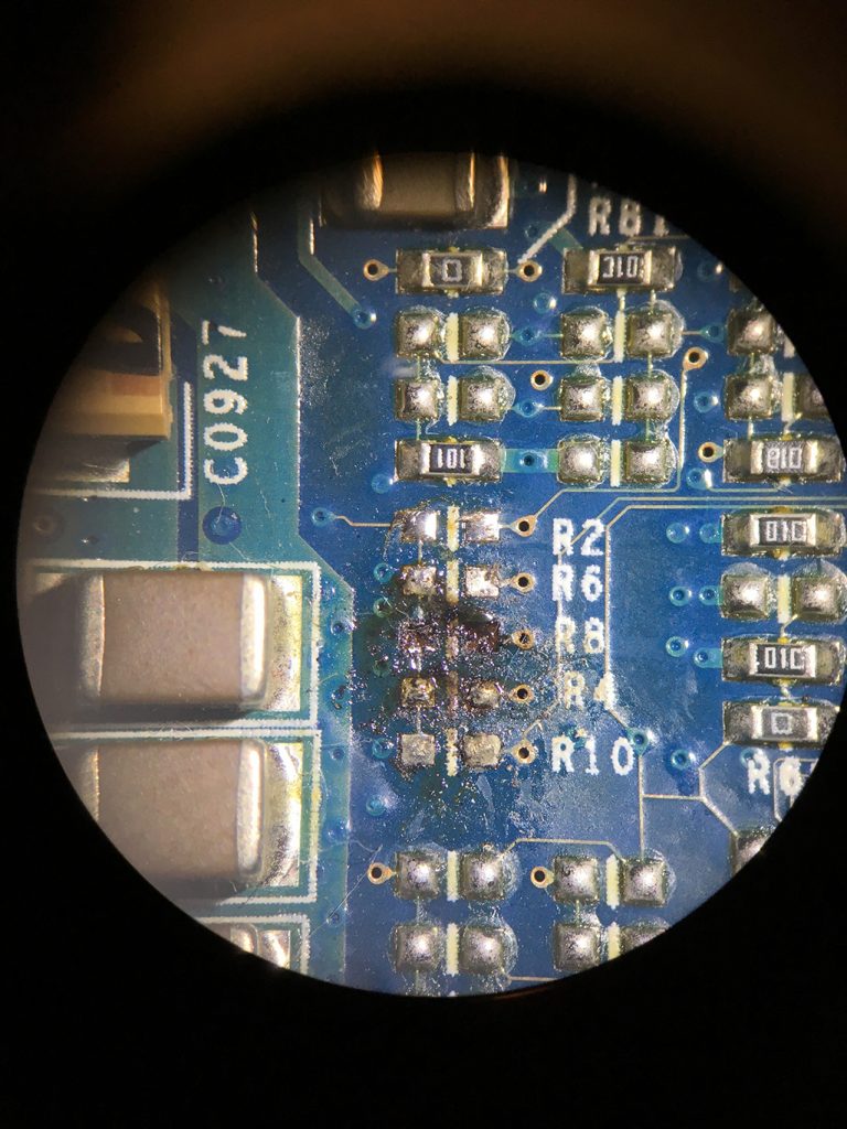
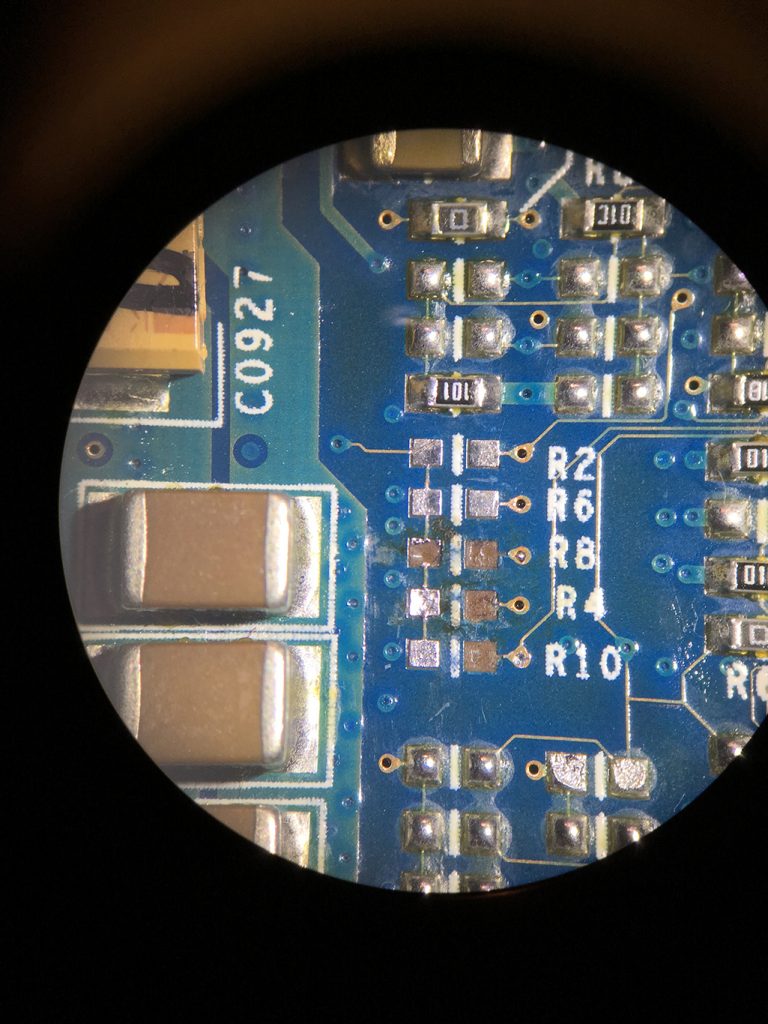
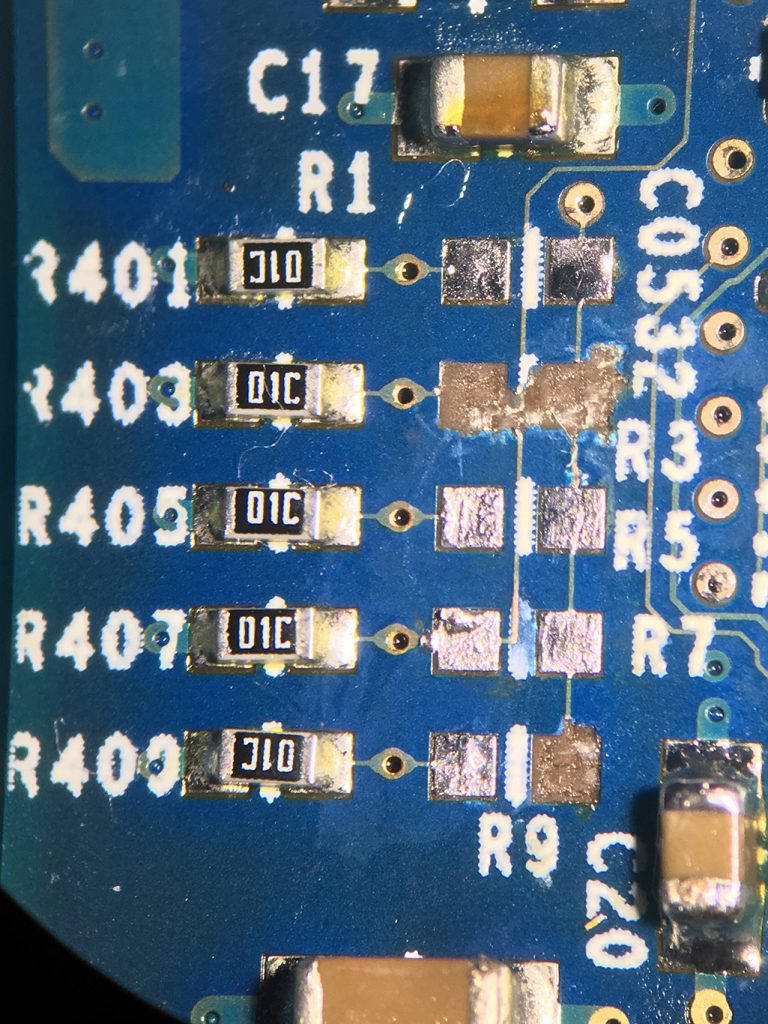
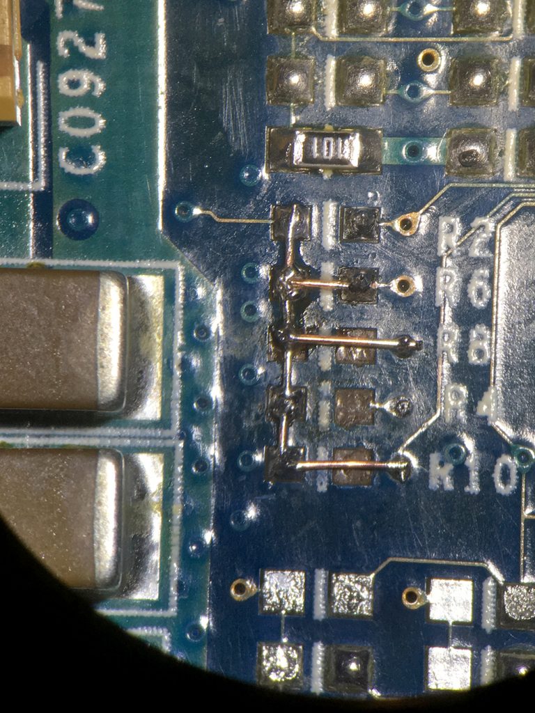
Second, cleanup to see what is left to work with and what needs to be repaired.
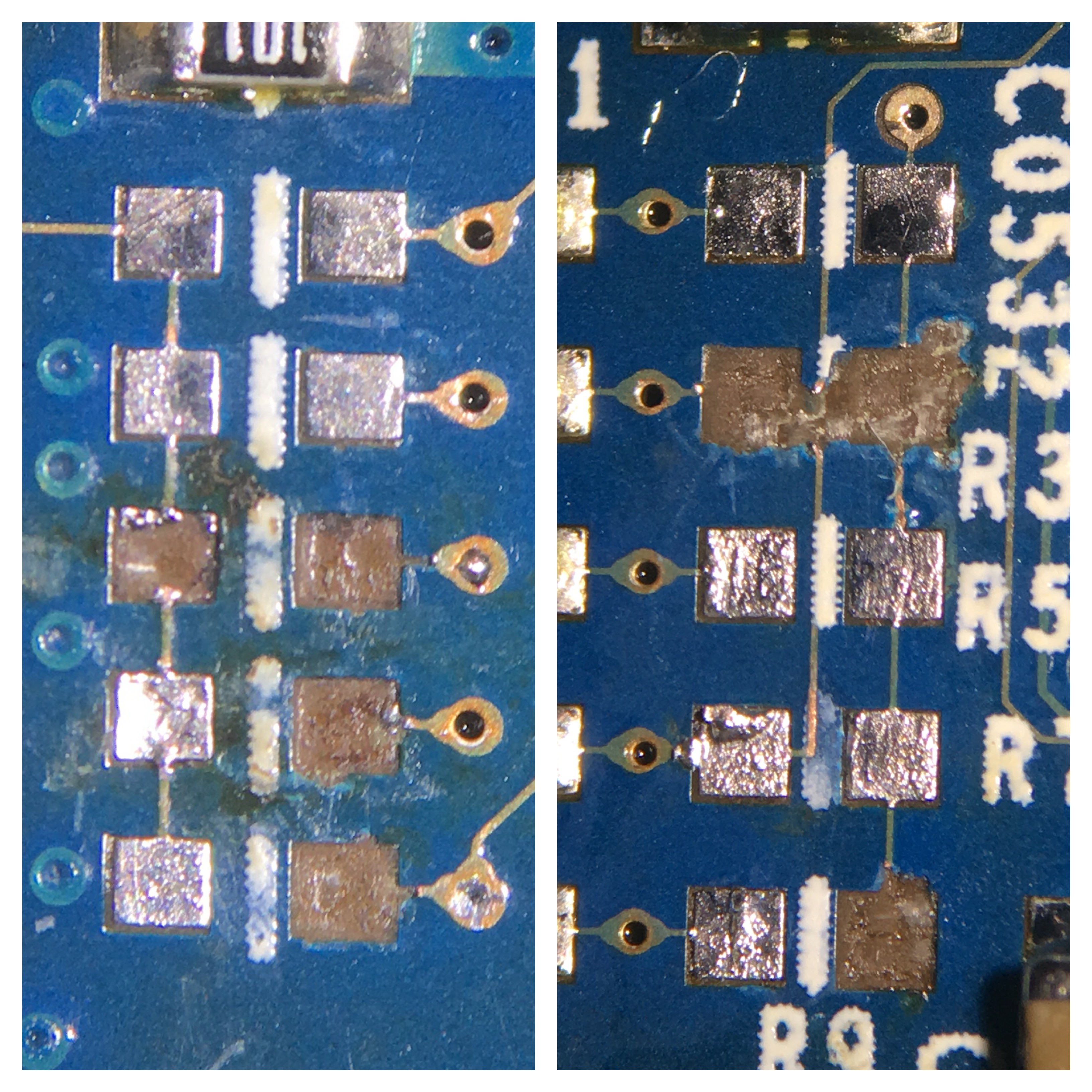
The front shows the center pad in the left column missing, breaking power delivery to the bottom two pads. Also the three pads in the right column are gone. The missing pads are not an issue as we can solder directly on to the probe points next to it but the left column has nothing in that center pad to solder on to.
The back shows two broken traces that both need to be repaired to restore function, a little trickier due to the positioning of the center trace.
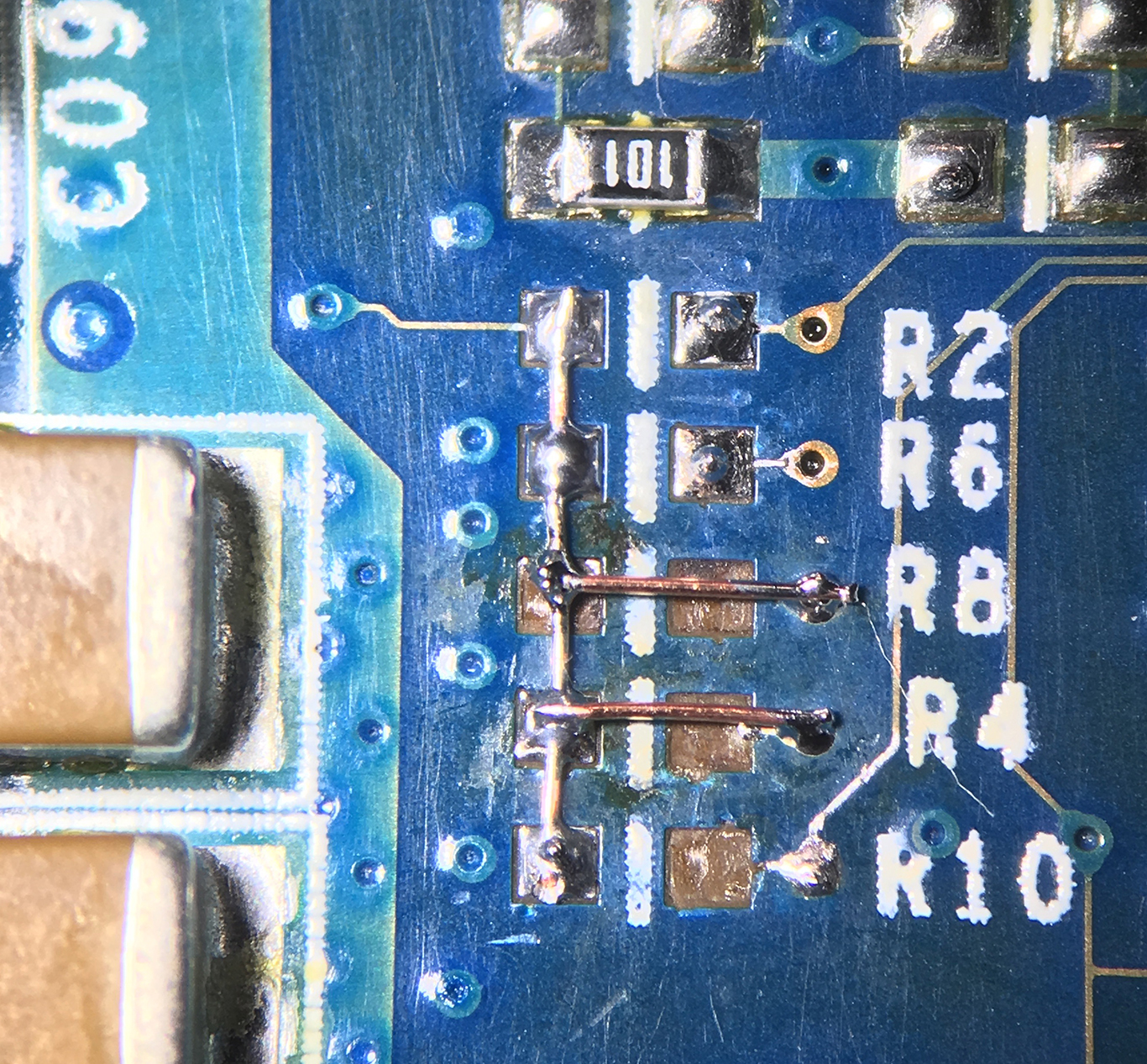
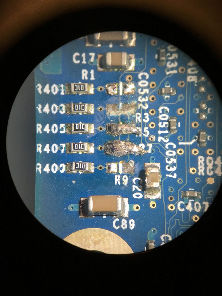
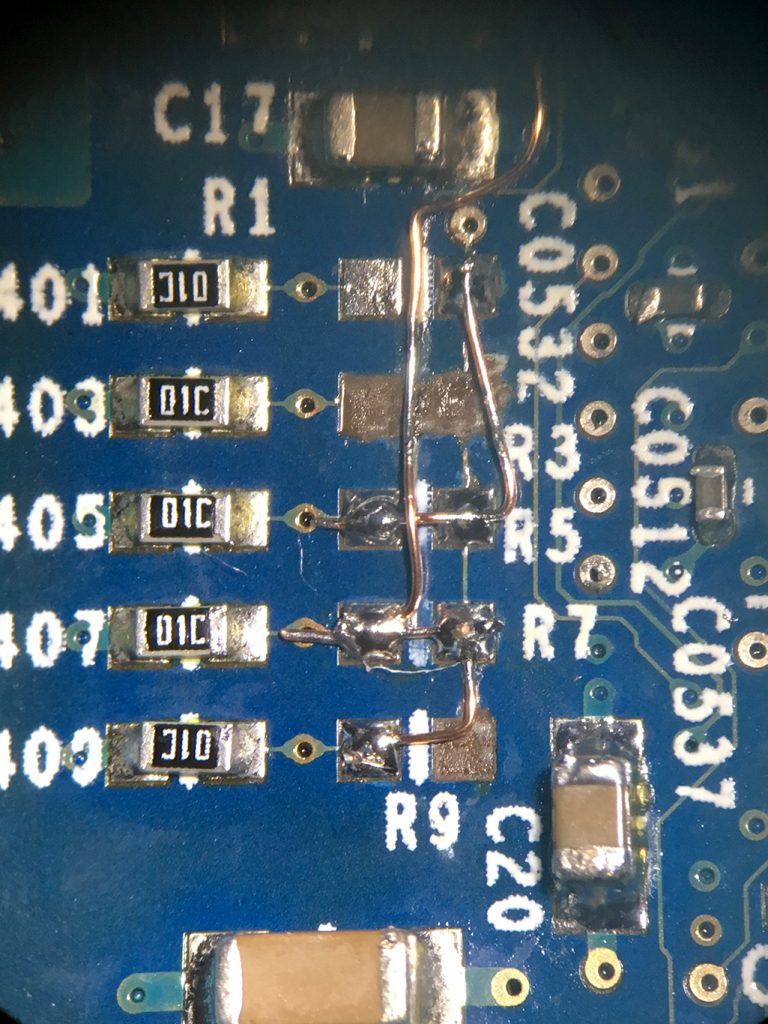
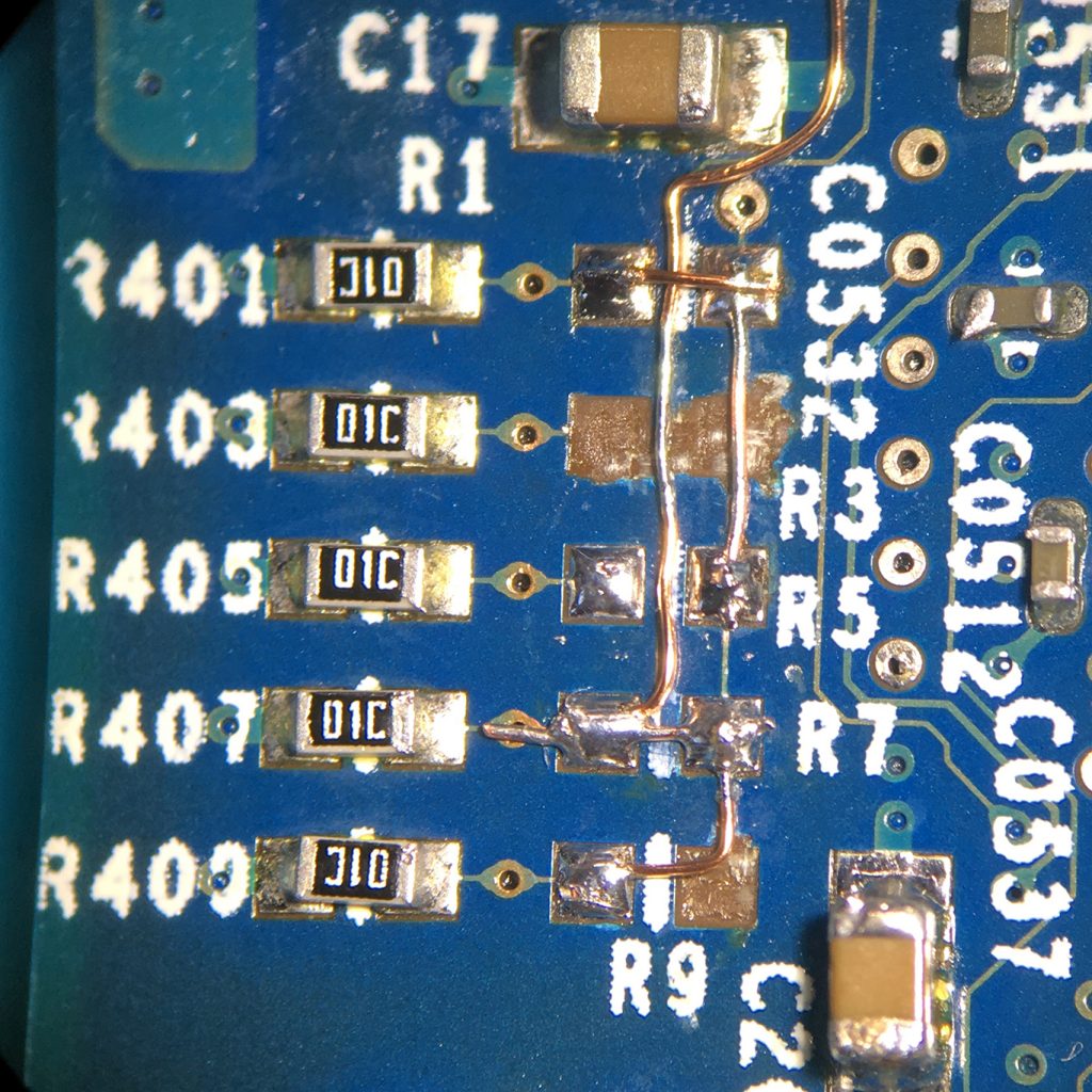
Third, repairing the broken traces and restore power to where it needs to go. Greg stated to know which pads needed to be bridged to get an overclocked result, so that’s what I did. Here is the front:
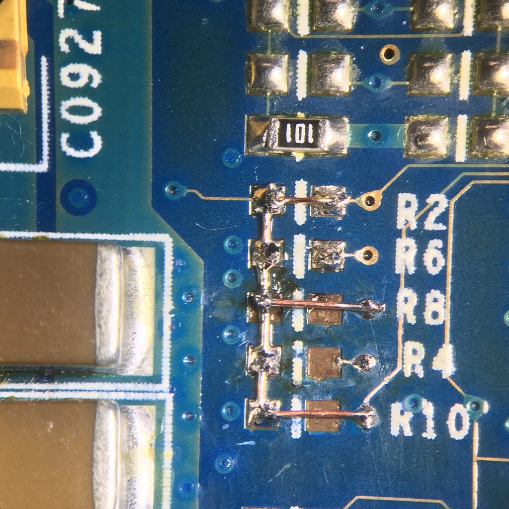
And the back:
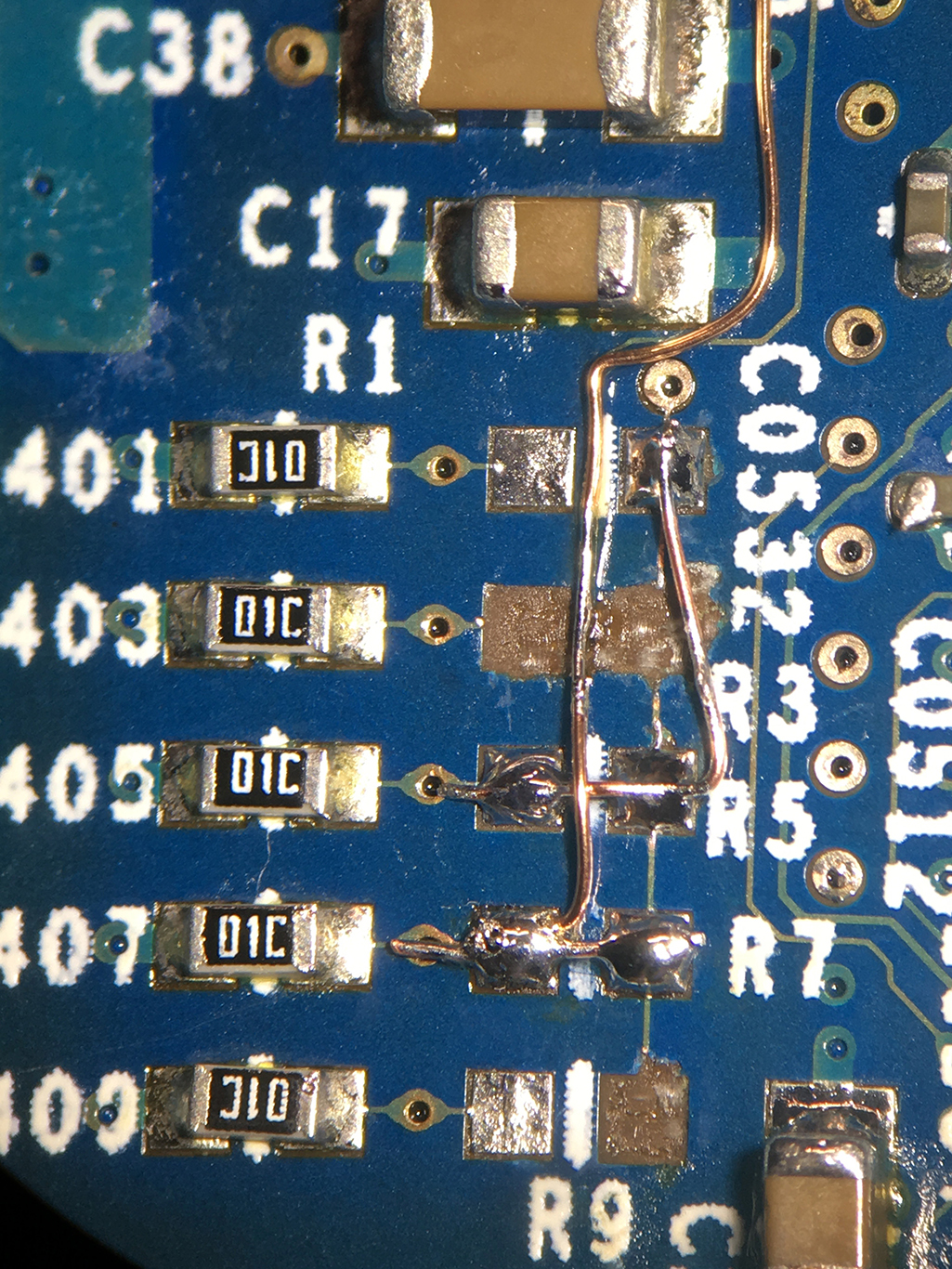
The center wire restores the path from R7 to R1 and up to the origin point for added stability. The wire at R7 acts as the bridge between the pins and the wire at R5 acts both as a bridge and a trace repair to R1. These are insulated wires of course so having them cross is not an issue.
That should do it. Some fresh thermal paste was applied and the card was seated in a Power Mac G4 MDD.
Nothing, just loud fans. The documentation was studied a bit more and I figured out where the bridges should actually go. With this new, hopefully accurate information both sides of the card were adjusted.
Test number two went better, the Mac booted up and displayed the correct information.

Greg was notified the card was repaired and overclocked to it’s desired clock speed. The decision was made to push it a little further so back to the bench it went.
Let’s see…
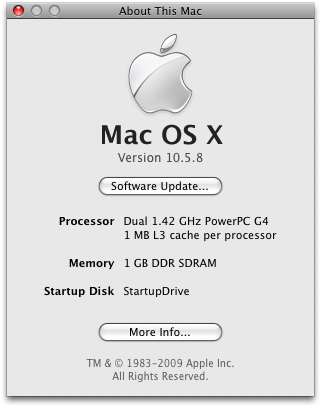
Nice, overclock to dual 1.42GHz was a success. But is it stable? It may need voltage adjustments so both CPU’s were subjected to an hour of pretty serious choke-worthy testing (YouTube 720p playback and Grapher). The card ran every test just fine.
At this point it was decided to not push our luck any further and leave it at 1.42GHz. Though we felt 1.5Ghz is doable (most likely with voltage adjustments for that clock speed), Greg has plans for the card at it’s current speed.
Now overclocking an undamaged card can be done with jumper wires as well but using a 0 ohm resistor will look neater. I might actually try this on my own dual 1.25Ghz CPU card as well.
As for the jumper settings to overclock, here they are:
These images are based on an 820-1470-A dual 1.25GHz CPU card. They have been confirmed by various people online to work on any dual MDD/G4 X-Serve CPU card. Use the above linked resources to identify the right banks to start soldering in, also use those resources if you want to mess with voltage adjustments as I will not cover those. Depending on your starting point you will have to make voltage adjustments. A dual 1.25GHz can go up to 1.5Ghz probably without needing voltage adjustments, a dual 1.0GHz may require voltage changes at 1.33GHz etc. Also keep in mind the bus speed of your card dictates the final overclocking speed or any given jumper settings.
To elaborate on that; if you have a dual 867MHz card, the bus speed is 133MHz. If you have a dual 1.25GHz card, the bus speed is 167MHz. You can make the same jumper changes on both cards but they will result in different speeds. To get the speeds in my image, you need a bus speed of 167MHz which will require a modification of both your CPU card and your logic board. Such modification is beyond the scope of this article but a good table can be found here.
Finally, make sure your heatsink is adequate for the new clock speed, use a solid aluminum block or copper heatsink at least.
This information is provided with no guarantees. It may work, it may break your card, I may be wrong about the jumper settings etc. Use this information at your own risk. Click the image for a full sized render.

-= The overclocking bit of the article ends here =-
Two-coil VS three-coil CPU card designs.
It has been said that these CPU cards with 3 coils are harder to overclock than those with 2 coils. But why? (spoiler: I don’t know) And what is the difference between the cards? I was curious and decided to investigate a little. First, here are the two card designs side by side. Click on the images for full size high res versions (about 8MB each so give it a sec to load).
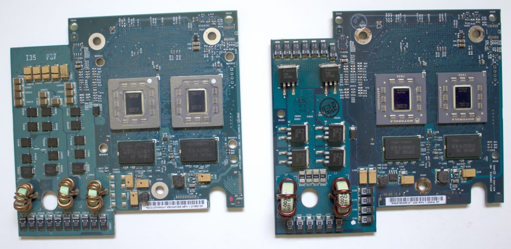
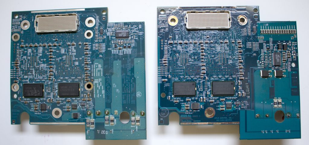
Of course the obvious differences are the six large MOSFET’s on the 2-coil card. The 3-coil card uses twelve smaller chips and three slightly bigger ones. Presumably this is for smoother current control to the CPU’s. The 3-coil card appears to handle this all on one side of the card whereas the 2-coil card has two MOSFETs on the other side of the card as well.
The 3-coil card is actually of a newer design than the 2-coil card. Both cards are stamped 2002 but the CPU cards that came after reverted back to the 2-coil design. The hypothesis is that Apple tried a thing with these cards, failed and almost immediately went back to the old design that worked just fine to begin with. Perhaps cost saving reasons, who knows. The CPU cards that came before are also 2-coil designs with the large MOSFETs.
Sorted by part number:
2002 MDD FW400 – 2-coil design, less but larger chips / 2001 / 820-1310-A (old board stock with newer CPU’s?)
2001 Quicksilver G4 – 2-coil design, less but larger chips / 2001 / 820-1324-A
2001 Quicksilver G4 – 2-coil design, less but larger chips / 2001 / 820-1344-A
2002 MDD FW400 – 2-coil design, less but larger chips / 2002 / 820-1452-A
2003 MDD FW800 – 3-coil design, more but smaller chips / 2002 / 820-1470-A
2002 MDD FW400 – 2-coil design, less but larger chips / 2002 / 820-1472-A
2003 MDD FW400 – 2-coil design, less but larger chips / 2002 / 820-1497-A
Most 733-867Mhz cards and older use a single coil design but still use the larger MOSFET chips.
The only CPU cards with a 3-coil design are labeled part number 820-1470-A. These are:
Dual 1.25GHz for a FW800
Dual 1.42GHz for a FW800
Dual 1.33GHz for an X-Serve G4
Greg dragged his butt out of bed to check his single 1.33GHz CPU card for me but that one is a 820-1497-A.
Whatever Apple did on these cards make it less ideal candidates for overclocking. Yet it can still be done as seen in the first section of this article. If overclocking is your goal though, I’d stay away from 820-1470-A cards for higher chances of success.
So what happened to Greg Hrutkay’s logic board?
I said I’d circle back to this so here’s the skinny. When Greg removed his CPU card while cleaning the Mac, he noticed a pretty serious discoloration on the card.
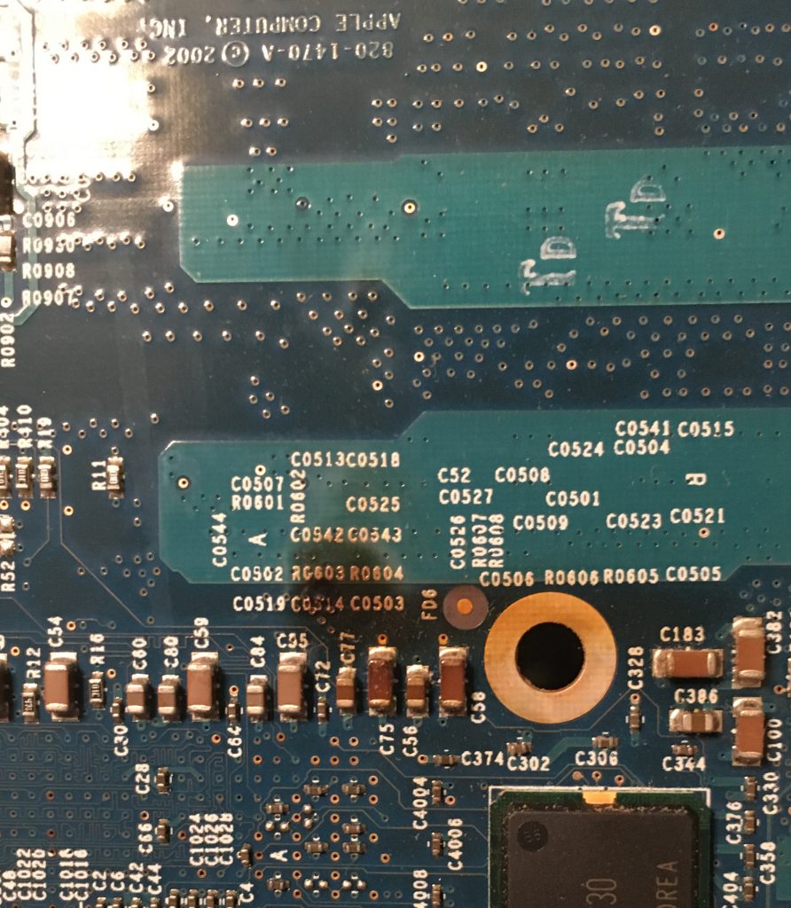
As the components on the card appeared fine, he checked the board itself and found the following:
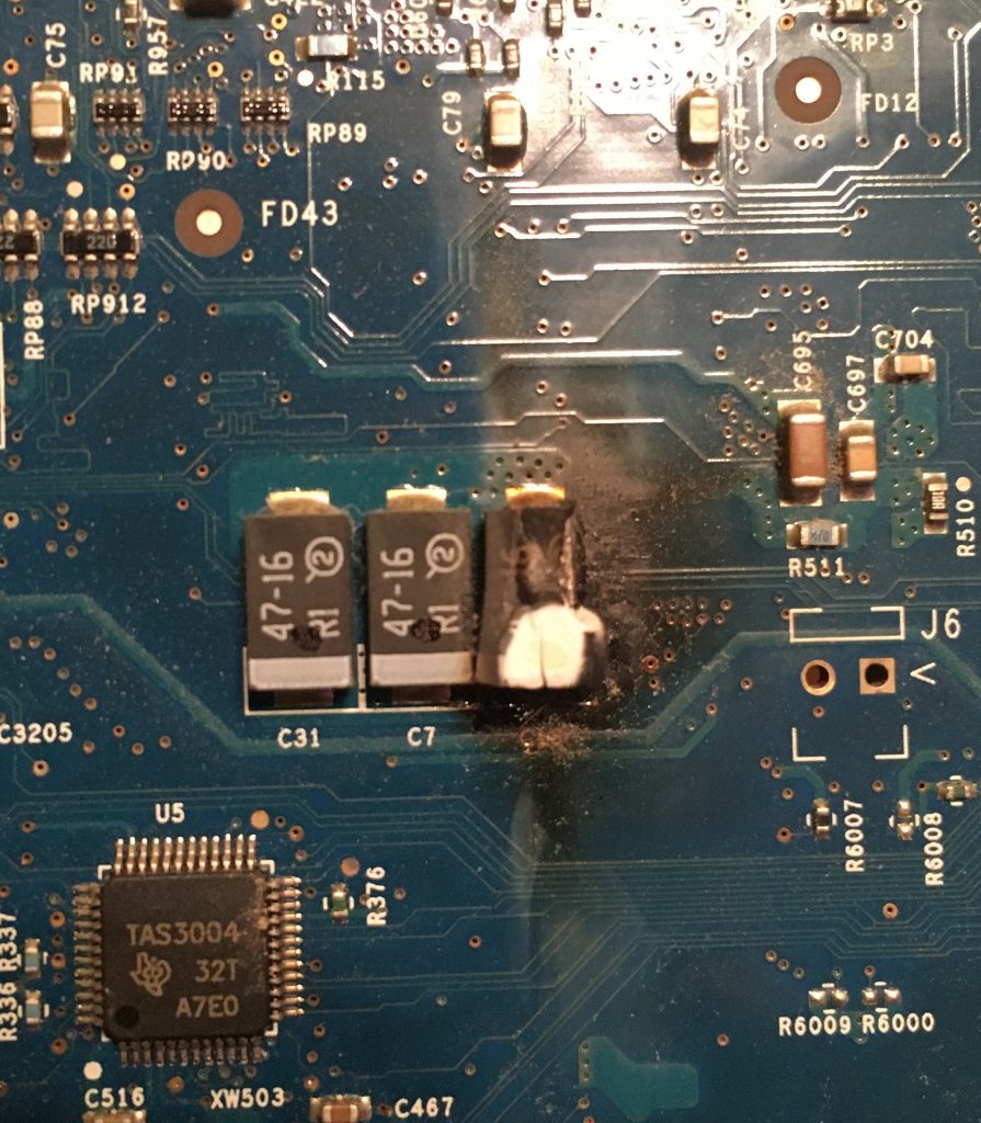
A capacitor went pop and scorched both the logic board and the CPU card. The soot was cleaned and a new capacitor was soldered on.
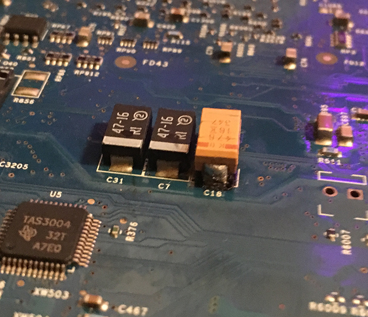
After extended testing the capacitor held and this board is considered repaired!
When I received his CPU card I noticed the other side of the card became so hot that several components popped out solder balls (happens with higher than normal heat exposure) and oozed flux from underneath them. I forgot to take a photo of this 🙁 I re-attached the worst of the affected chips and cleaned up the flux (brown/yellow goop). Luckily none of the chips went bad, they just got cooked a little. I don’t know if the other side of his logic board saw similar effects from this heat but everything appears to work properly.
There you have it, another fun project completed! Let me know if you’ve done any overclocking and what the results were.
Did you like this content? |

2 thoughts on “Reviving a fried Power Mac G4 CPU card”
In my defense the giant soldering iron work great for the other MDD OC to 1.5… Also the 3 coil dual 1.25 had 1MB of L3 Cache vs the 2 coil dual 1.25 which had 2MB of L3 Cache… The 3 coil 1.25 is the only 3 coil card with 1MB of L3, the 1.33 and 1.42 both have 2MB of L3
Nice work Jay, great job repairing the G4 CPU board.