Figuring out the PowerBook G4 hi-res overclock
So, I’m stuck. Well not really stuck but I do not have enough time available to invest into figuring it out. So I figured I’d write this up and maybe the awesome community can help me out 🙂
Once this is figured out I can probably document the process and add it to the PPC Overclocking Station page where everyone will be able to enjoy it.
Searching the interwebs you can find plenty of references to this. Sites like Macrumors and Overclock (other sites as well) all reference the same information when it comes to jumper settings which is taken from the official board schematics from Apple. I have those schematics as well but when I sat down to do the overclock, I ran in to a problem. Below I will outline the problem.
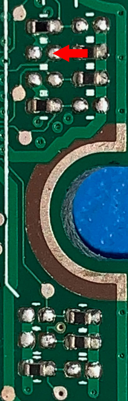
All references I have found online talk about the clock speed jumper settings that are detailed in the schematic:
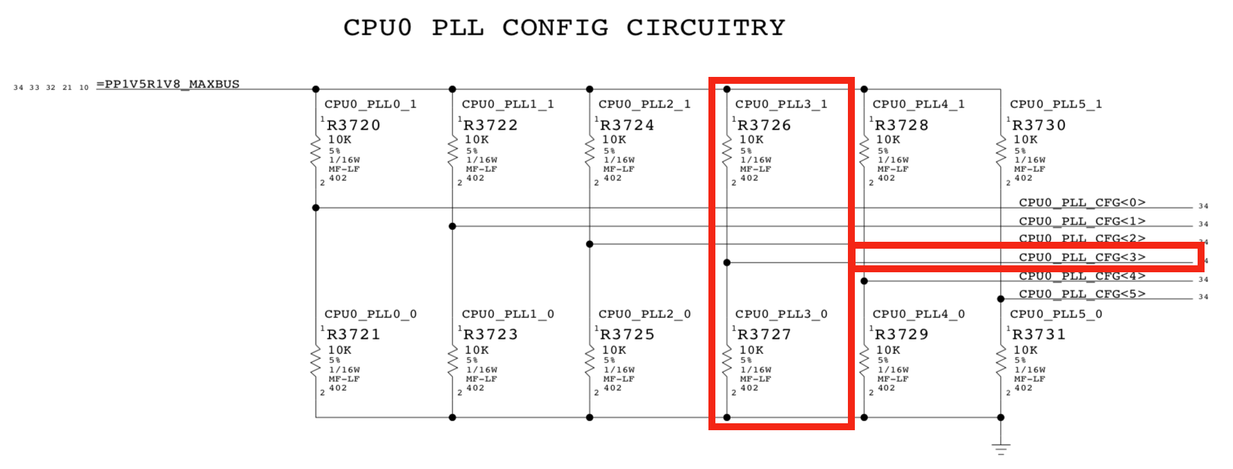
R3726 and R3727 that make up PLL_CFG<3> however, do not exist on the board. At least not on my board.
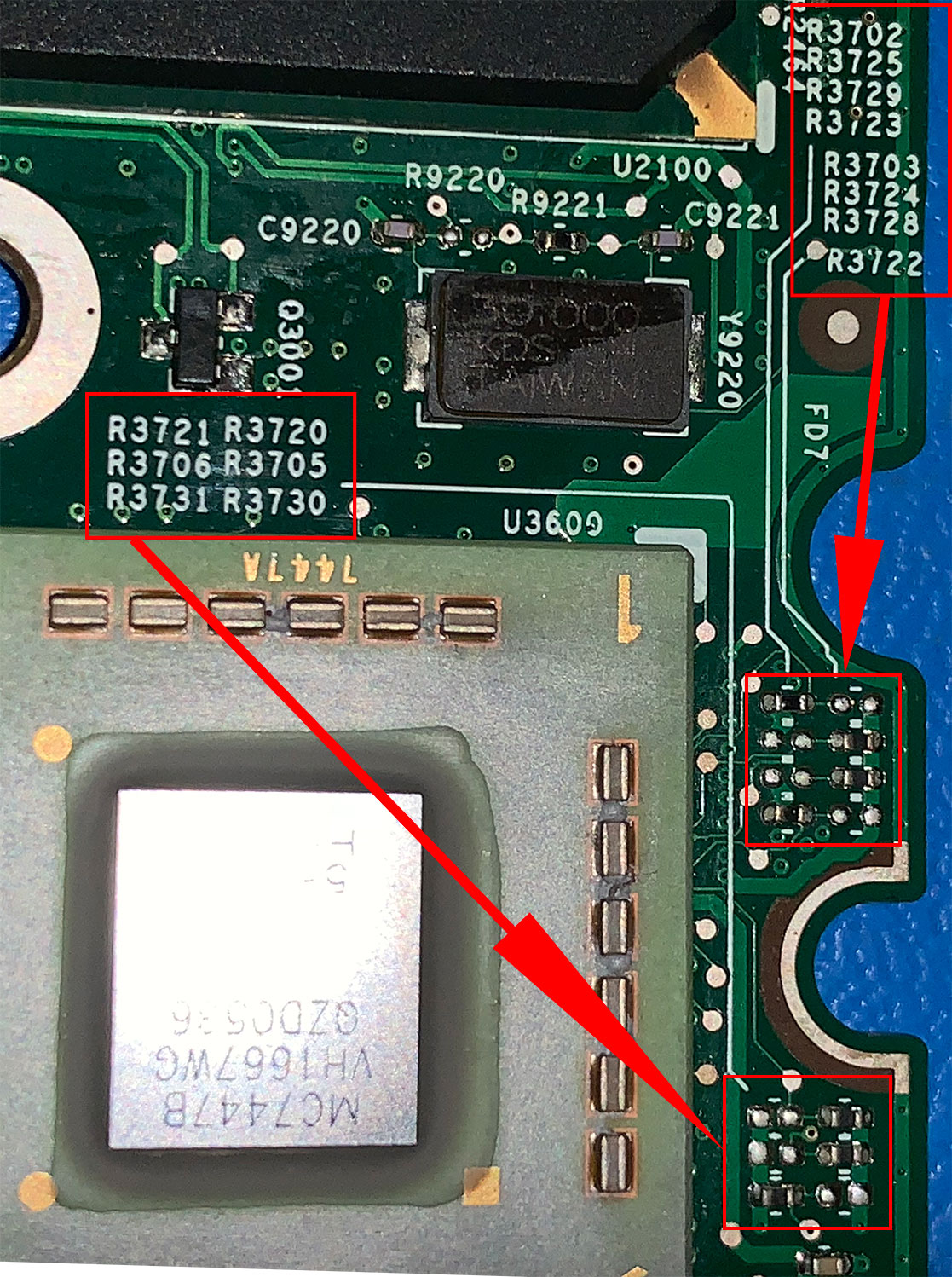
Which leaves me with:
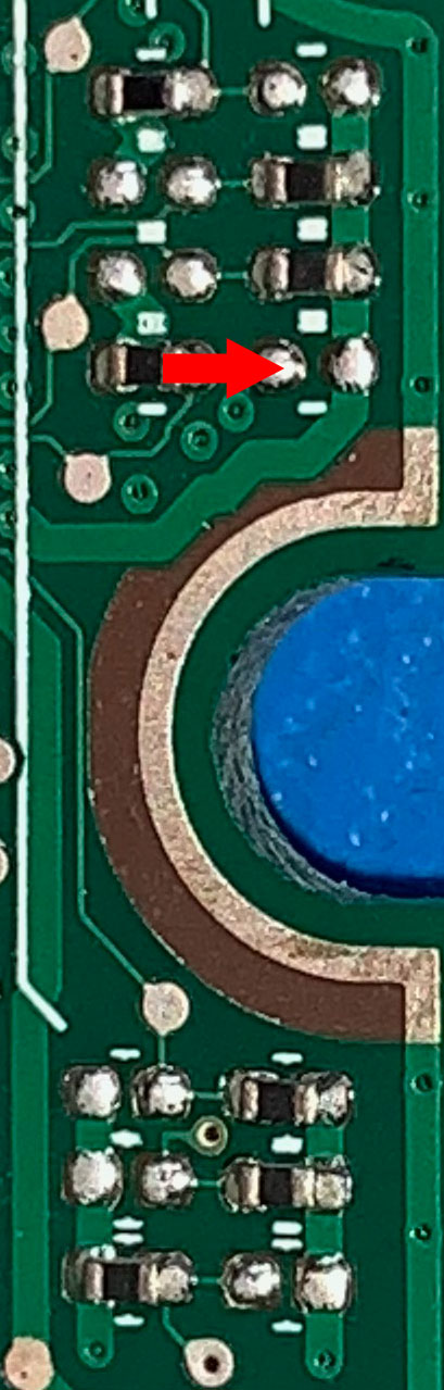
At the top we have R3702 + R3703 and at the bottom we have R3706 + R3705 that can be PLL_CFG<3>
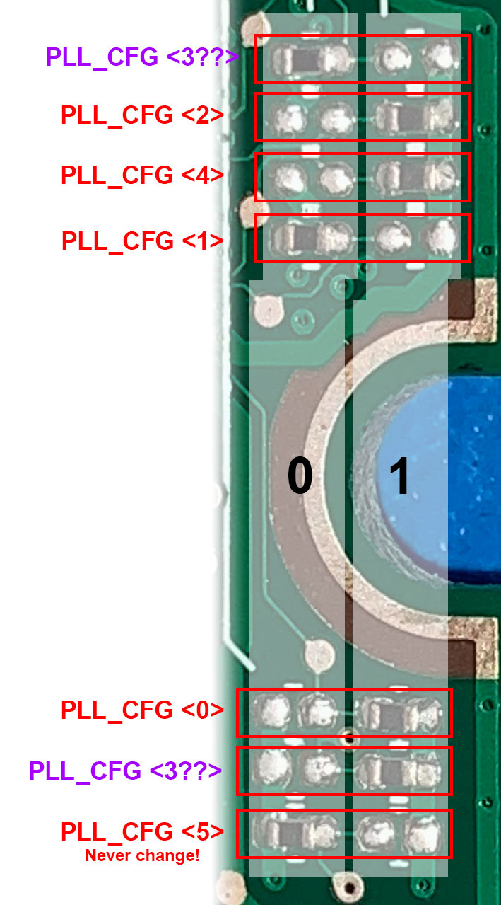
In it’s current configuration, if the top is <3>, the jumper configuration is: 101010 which according to the schematics is a 10.0x CPU to bus ratio.
However if the bottom one turns out to be <3>, the jumper configuration is: 101110 which translates to a 12.0x CPU to bus ratio.
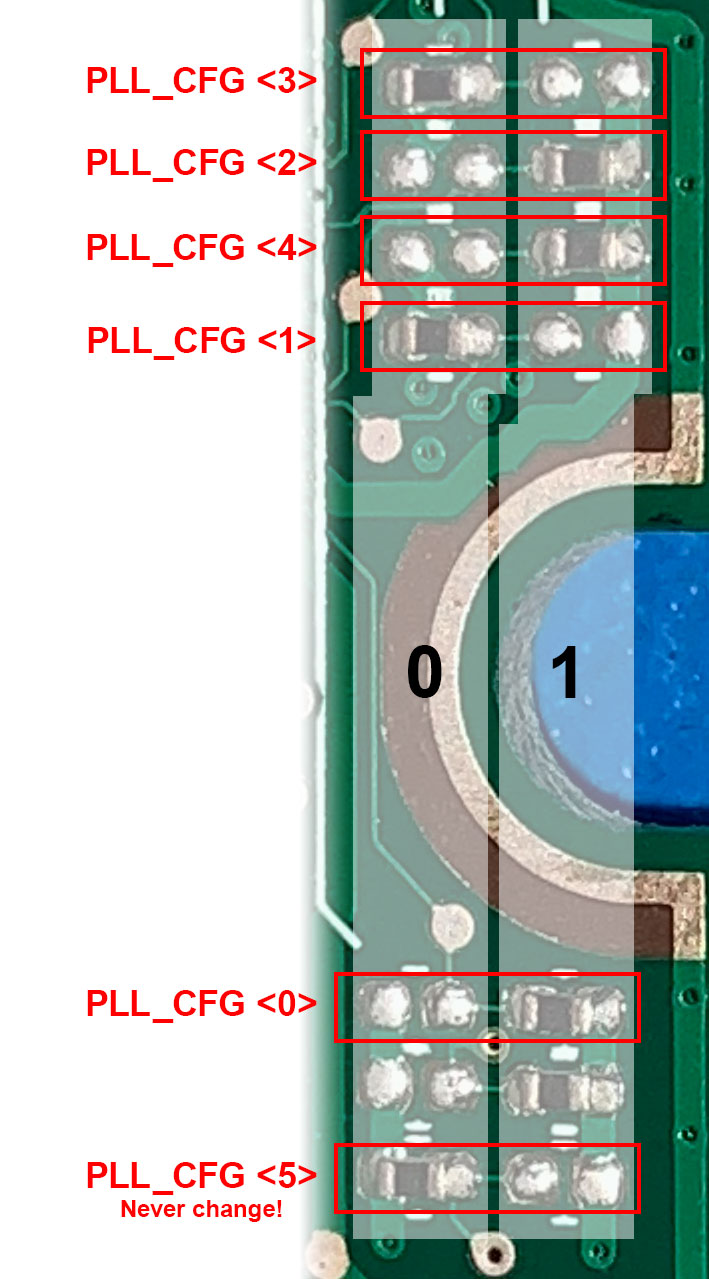
By the way jumper settings on this board don’t work like those seen on many other board. Typically 0=a jumper, 1=no jumper. Look at this board more like a light switch though.
From the orientation of the image I used, the left column of resistors equals 0 (on), the right column equals 1 (off).
A resistor is either on the left side or the right side for on/off, never on both sides.
Figured I’d clear that up since I do not want to assume everyone reading this has the same experience with overclocking 🙂

Now I can try both configurations that follow the configurations above, which depending on which block is <3> are 100010(10.5x) and 111110(12.5x). Then see which one results in a booting system with a clock speed higher than 1.67GHz but I simply do not have the time.
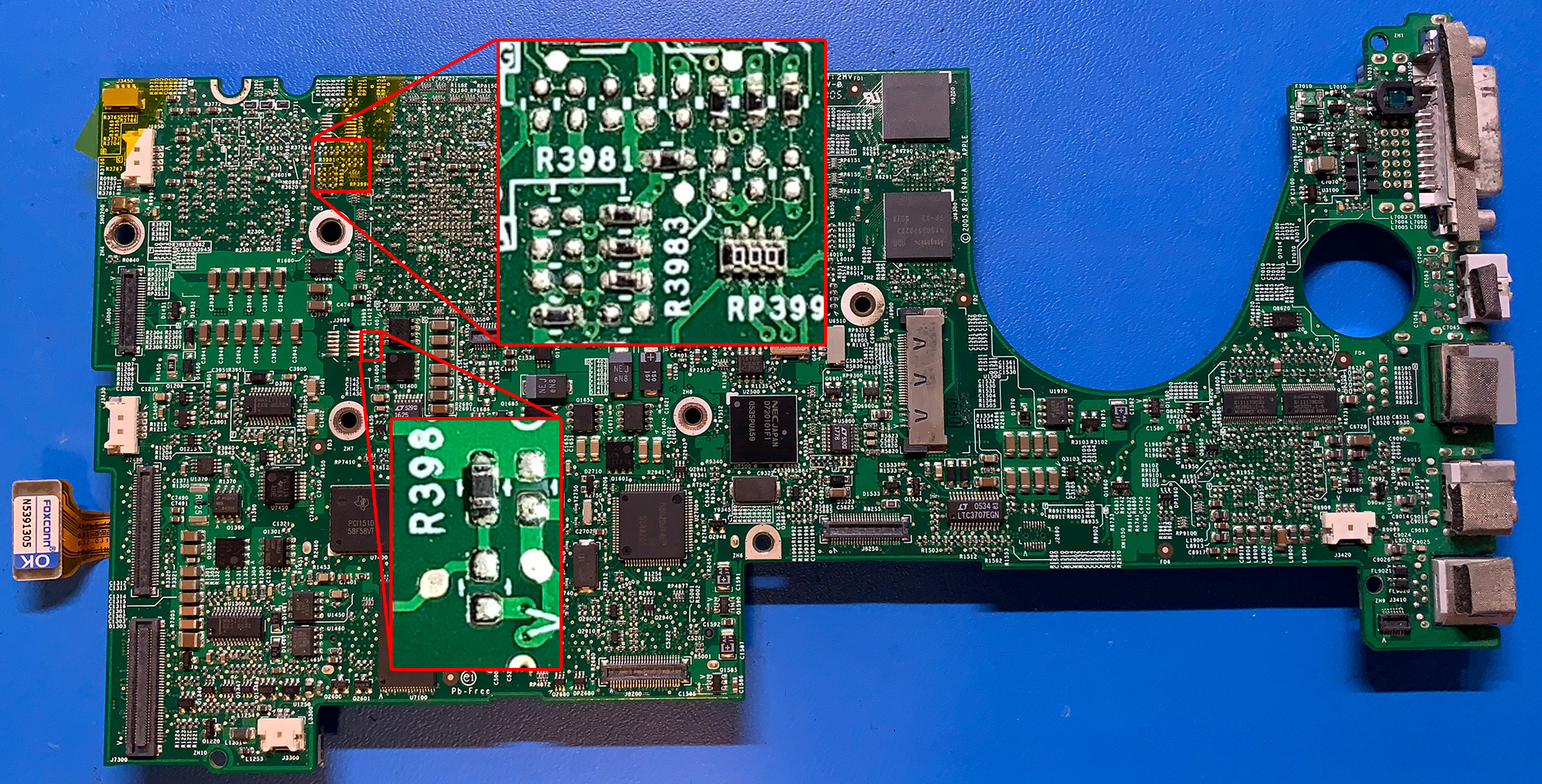
If you want to help figuring this out, the schematic for the PowerBook G4 (15-inch Double-Layer SD) 1.67GHz can be found on this website. Look for ” PowerBookG415High-Res.pdf 1414k .pdf”. The board in my Hi-res is an 820-1490-A and here is a photo of the bottom:
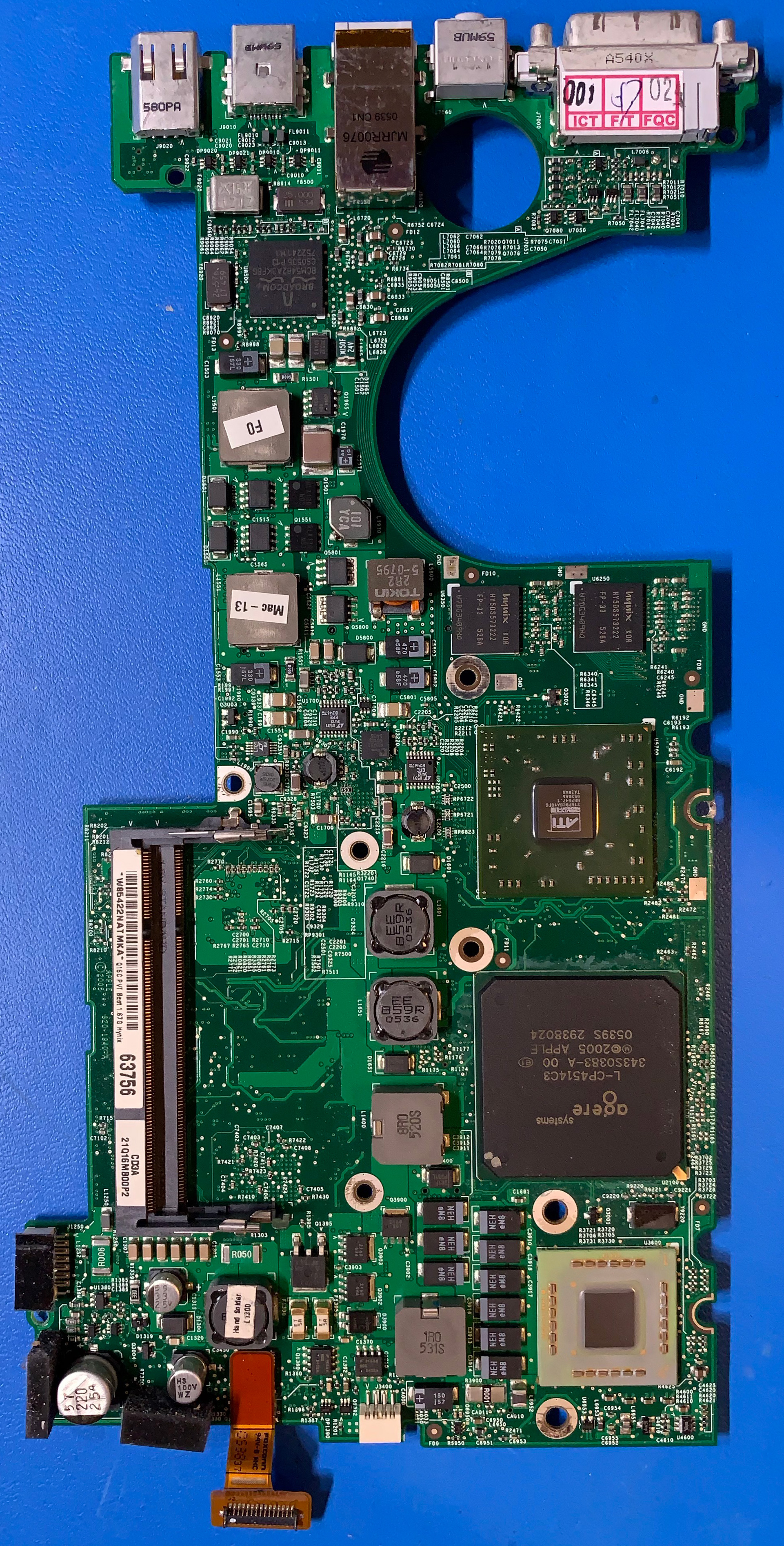
I also have a board view file for this model but have been unable to open it as it’s ancient and requires software on a specific OS I do not have.
Let me know in the comments what your thoughts are. Or if you have done this overclock yourself let me know so I can fish the info from your brain directly 🙂
Update:
Made an attempt. A mentioned above there are two configurations to test with the hopes that one works, so I tried the first: 100010 (10.5x).
The Mac POSTs but the HDD does not spin up, the display stays black and the Caps Lock light remains on. Next up is to try 111110 (12.5x).
This resulted in no POST and fans blasting full speed. So definitely not a valid configuration. Since the 10.5x configuration did POST, right now I am leaning to this being the right jumper labeling:
Which would mean the R3726 and R3727 mentioned on all those other websites and the schematic is actually R3702 + R3703. Combining this with overclocking information from other (earlier) PowerBook G4’s that mention 1.67GHz as being a 10.0x ratio, I think this part has been figured out. Now to get it to work…
Update 1:
So I ended up spending the time I didn’t have anyway….
To get this working I think I need to bump the voltage, so time to search for the non-existent information on that and circle back to the clock speed after that.
The schematic shows that chip labeled U3900 handles Vcore This is a Maxim 1717 chip. Once you’ve overclocked a few machines you get pretty good at spotting the Vcore chip on a board as it’s layout will be familiar. On this board, here it is:
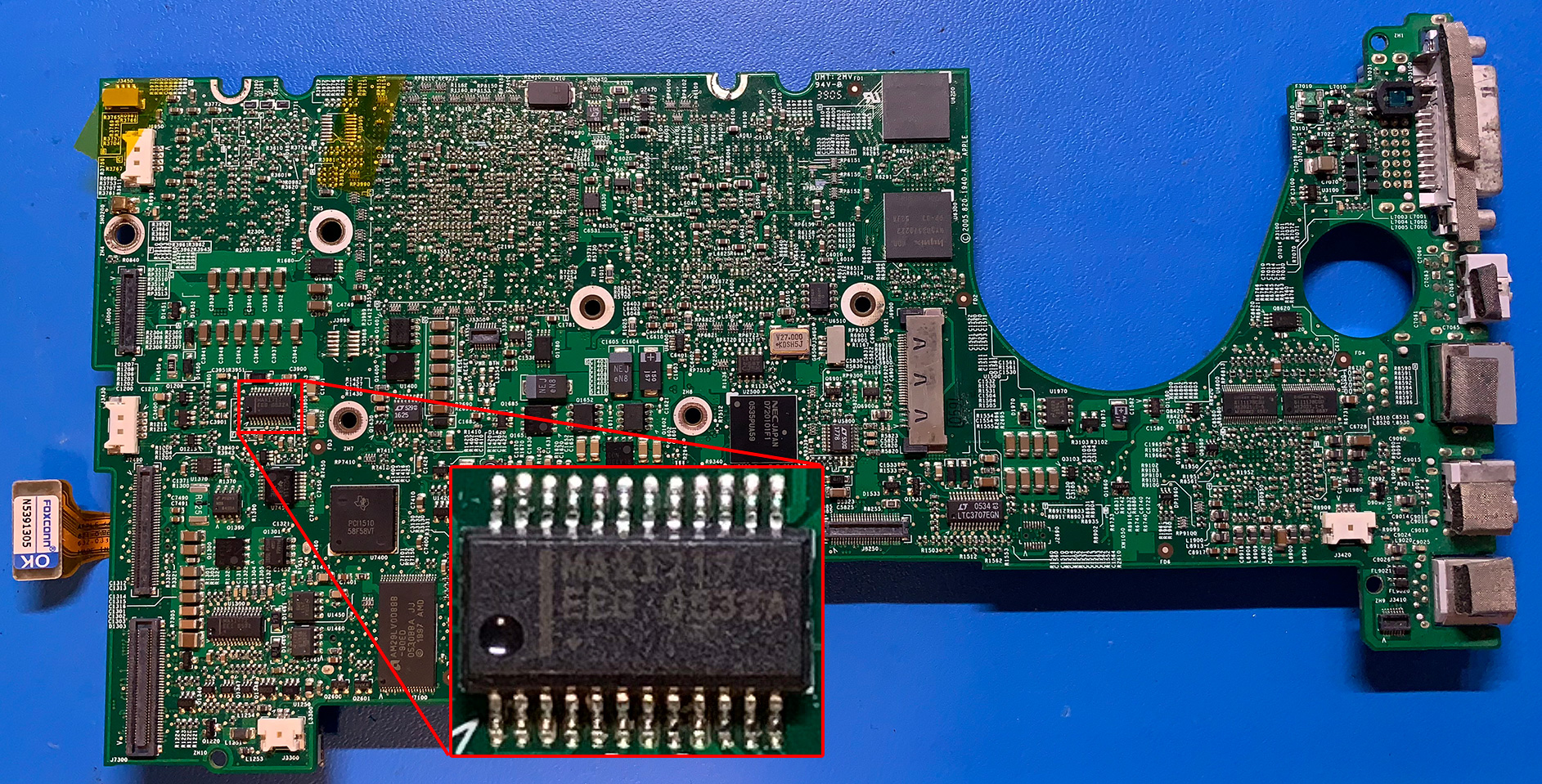
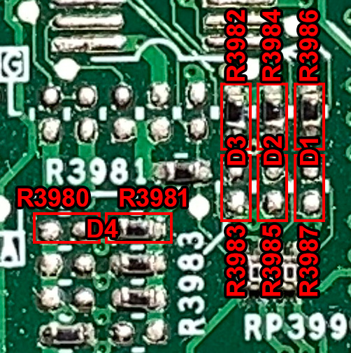
According to the schematic pins 17-21 handle the voltage settings. These pins are here:

Pin 17 -> D4 -> R3980†+R3981
Pin 18 -> D3 -> R3982+R3983†
Pin 19 -> D2 -> R3984+R3985†
Pin 20 -> D1 -> R3986+R3987†
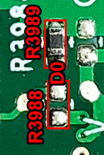
Pin 21 -> D0 -> R3988†+R3989
† indicating a resistor should not be present there according to the schematic.
Of course it would be far to easy if the resistors were directly next to the chip. Yeah, they are somewhere else on the board entirely. Namely here:
The current configuration for a 1.67GHz Hi-Res PowerBook G4 = 10001
When we look up 10001 in the MAX1717 data sheet we see that configuration = 1.250V
Bumping it up one step to 1.275V will hopefully show if my earlier clock-speed changes (1.75GHz) are working. If they are, the clock speed settings and voltage settings have been figured out and we can start overclocking!
Update 2:
The new clock speed at 1.275V results in POST but no image, no HDD spin and caps lock light on. At 1.30V the fans just blast on Max. Either I misidentified PLL_CFG<3> or this CPU just doesn’t like doing 1.75GHz and I should Try 1.83GHz at 1.30V next. For now it’s back to the drawing board.
One thought on “Figuring out the PowerBook G4 hi-res overclock”
Hello!
Thanks for interesting article. Are there any update?
I checked the Powerbook G4 schematics, and found there that resistors mentioned above in red boxes are:
R3702+R3703 = MAXBUS VSEL (switching between MAXBUS_1V5 and MAXBUS_1V8) – this is probably connected with CPU bus voltage setting 1.5 or 1.8V (according to 7448 HW spec)
R3705+R3706 = switching between CPU_A7P and CPU_A8 ( it is probably 7447A/B and 7448)
So they are NOT the missing PLL_CFG_3. They have to be somewhere…
If we don’t find them, I recommend avoid frequencies where PPL_CFG_3 are changed.
I.e. if this last Powerbook have 166 MHz FSB, i.e. multiplier PLL_CFG CONFIG [0:5]= 101010 it is x10 by default, we can without change of PLL_CFG_3 ( 0 is here ) try combinations:
10.5x, 11.5x, 13.5x
or if we with CPU 7448 only succseeds to change FSB to 200 MHz:
also 8.5x and 10x